Extinguishing Control Computer 8010 – 19-Inch
26 FB 798955.GB0 / 09.07
5 Mechanical configuration
The Extinguishing Control Computer 8010 is suited for a direct mounting to a 19-inch rack. The arrangement of
the appropriate operating elements and connectors does not require to open the housing.
The housing must be opened only for the required jumper settings and to insert the batteries. All
internal cable wiring is done by factory.
5.1 Operating- and connecting devices
12345678
9 10111213
Fan trouble
1
4
7
0
8
5
23
6
9
0 0 0 5
Relay (AE) 1
2
3
4
5
6
7
8
9
10
11
12
13
Unlocked
Disconnection
In operation
Switching off
Test operation
Extra releasing 1
Outputs
Alarm
Switchover
Buzzer off
Lamp test
Zone
Output
Panel reset
On
Off
Test operation
Common t rouble
Emerge ncy
operation
Powe r trouble
Battery trouble
Groun d fault
Trouble 1
Blocking
Emergency release
Detector zone
Fire/Switch off/Trouble
Extinguishing system
activated
Extinguishing system
enab le d
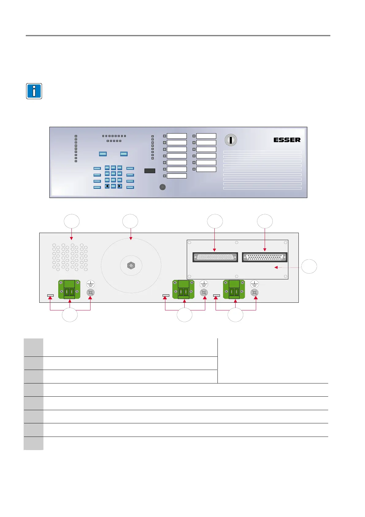
Fig. 18: Housing (Front view)
Netz
Relais 12 Relais 13
68 57
1 2 3
4
Fig. 19: Housing (Back view)
c
Connector for the 230V AC mains voltage (L1/N) and separate
mantle terminal for PE connection
d
Terminal for the 230V AC-voltage relay 12
e
Terminal for the 230 V AC-voltage relay 13
Led cable to the appropriate cord grip!
f
Terminal card with 50-pole D-SUB connectors to the external terminal for zones and relays
g
50-pole D-SUB jack Î relays or control outputs
h
50-poliger D-SUB plug Î zones
i
Toroid transformator
j
Ventilation holes

 Loading...


