Extinguishing Control Computer 8010 – 19-Inch
FB 798955.GB0 / 09.07 35
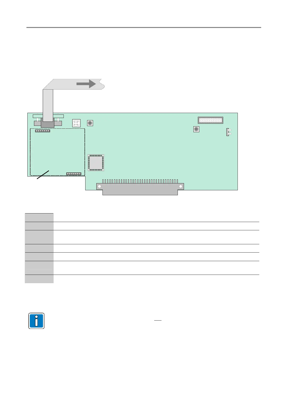
7.1 Processor board
The processor board is connected directly to the zone board by a 64 plug connector. On the processor board
we find, among other things, the microprocessor for controlling the panel functions as well as the operating
system and the customer data EEPROM. The required internal wiring is done by factory. The connectors fort he
external terminal card are placed at the housings rear side.
RESET
S1
SERVICE
S2
X3
X4
X27 X28
U17
X13
X12
X29
Internal connection
to zone terminals
Door contact
To control and display panel
position for esserbus
®
-
communication transponder
Processor board
Fig. 26: Processor board / position of the subassemblies
X12
Connector for the ribbon cable to the display and control panel
X13
64-pol. pole terminal strip for connecting to the zone board (19-Inch)
X28
4- pole programming interface for Service PC.
This connector is also available on the operating panel.
X29
Terminals for the door contact of the cabinet (option)
U17
Operating system and customer data EEPROM
S1
Reset button (cold start)
By pressing the button a restart of the system will be initialized.
S2
Service key
7.1.1 Stop extinguishing procedure for test purposes by the operator
To interrupt a running extinguishing procedure for test
purposes hold down the S2 button (service)
and briefly push the S1 (RESET) button as well.

 Loading...


