Extinguishing Control Computer 8010 – 19-Inch
66 FB 798955.GB0 / 09.07
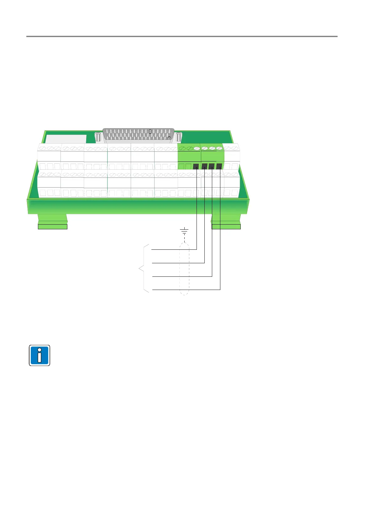
9 Analog loop connection
The Extinguishing Control Computer 8010 could be directly connected to the analog loop (esserbus
®
/
esserbus
®
-Plus) of the Fire Alarm System 8000 / IQ8Control.
The analog loop terminals are located on the external terminal card of the zones.
Up to eight Extinguish Control Computer 8010 (= 8 Extinguishing areas) could be connected to a single analog
loop of the Fire alarm system.
1234567891011121314151617181920
21222324
25 26
-
+
-
+
esserbus
®
UL+ out
UL- out
UL+ in
UL- in
PE
Fig. 47: Terminals to connect the analog loop wiring (type Phoenix)
To ensure a proper operation the cable shielding of the analog loop must be connected. For this
purpose one of the shielding-terminals of the detector zone terminal card may be used.

 Loading...


