Extinguishing Control Computer 8010 – 19-Inch
FB 798955.GB0 / 09.07 51
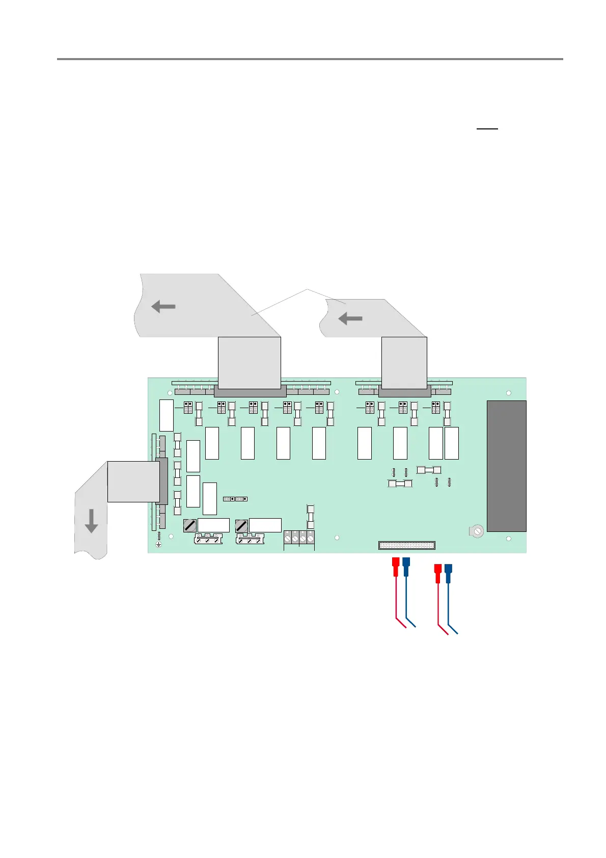
7.5 Power supply unit board and relay board
The combined power supply unit and relay board provides the entire voltage supply as well as the 13 Relay
outputs for control and status functions of the Extinguishing Control Computer 8010. The 230V AC mains
voltage must be connected to the appropriate terminals on the housings rear side and must
NOT be connected
to the power supply and relay board in the panel. An increased current requirement e.g. as a result of longer
cable lengths, must be compensated for if necessary by an external voltage supply via a separate power supply
unit.
The power supply of the Extinguishing Control Computer 8010 is monitored continuously of:
• Mains failure
• Battery charge
• Battery charge, current limited
• Earth fault identification (insulation)
dry
contact
moni-
toring
dry
contact
moni-
toring
dry
contact
moni-
toring
dry
contact
moni-
toring
dry
contact
moni-
toring
dry
contact
moni-
toring
dry
contact
moni-
toring
dry
contact
moni-
toring
GND 24V
UBEXT
+
-
+
-
F5 F6 F8 F9 F11 F12 F13 F16
F15
F14
Battery 1
Battery 2
F10
F2
F3
F4
F1
F7
to zone board
Poti
Power supply and Relay board
Emergency operation
X57
X47
X11
Internal connection
to relay terminals
Interal connection
to relay terminals
Battery1
Battery2
Fig. 37: Power supply unit and relay board
Terminals
The power supply and relay board is internally wired with the 50-pole D-SUB plug to connect the external
terminal card with the relay terminals 1 to 11 and both terminals of the mains voltage relays 12 and 13 at the
housings rear side.
Relay outputs
The power supply unit and relay board of the Extinguishing Control Computer provides 13 relay outputs for
switching and control functions. Status functions such as faults, deactivations, common fire or others of the
possible switching conditions can be assigned to the relays, whereby an OR logic operation of the individual
functions can also be programmed. All relay outputs are protected with separate melting fuses. The activation
time and the duration of each relay is programmable with the programming software.

 Loading...


