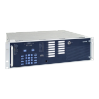
Extinguishing Control Computer 8010 – 19-Inch
52 FB 798955.GB0 / 09.07
Low-voltage Relay
Relay 1
Î
FuseF16
Relay 2
Î
FuseF13
Relay 3
Î
FuseF12
Relay 4
Î
FuseF11
Relay 5
Î
FuseF9
Relay 6
Î
FuseF8
Relay 7
Î
FuseF6
Relay 8
Î
FuseF5
T2 A /250 V
Monitoring
(factory setting)
or
dry contact
Relay 9
Î
FuseF2
Relay 10
Î
FuseF3
Relay 11
Î
FuseF4
T2 A /250 V dry contact
Contact rating
30 V DC / 2 A
Mains voltage Relay
Relay 12
Î
FuseF1
Relay 13
Î
FuseF7
T3,15 A /250 V dry contact
Contact rating
230 V AC / 2 A
F10
Fuses of the supply voltage for external units, UBext, T 3,15 A / 250 V
F14, F15
Fuses of the emergency power supply (battery 1 + 2)
Battery 1: F14, T 3,15 A / 250 V
Battery 2: F15, T 3,15 A / 250 V
J1 to J4, J6,
J8 to J13, J18
Jumpers to program the operating mode for relay 1 to 8, selectable to
monitoring or dry contact.
Factory setting = monitored relay
J5 (Relay 11)
Jumper to set the CPU-failure-mode function for relay 11 >Emergency operation fault<
Inactive = CPU-failure-mode function deactivated (factory setting)
Active = CPU-failure-mode function activated
J7 (Relay 10)
Jumper to set the CPU-failure-mode function for relay 10 >Emergency operation fire<
Inactive = CPU-failure-mode function deactivated (factory setting)
Active = CPU-failure-mode function activated
Poti
Potentiometer for adjusting the battery charging voltage 27.5 V DC (@ 25°C)
X47
Terminal for the ribbon cable to the zone board
X57
Plug for PE connection to the housings rear side
X11 / UB
EXT
Terminals for the Supply voltage for external units +24 V DC / GND

 Loading...