Extinguishing Control Computer 8010 – 19-Inch
58 FB 798955.GB0 / 09.07
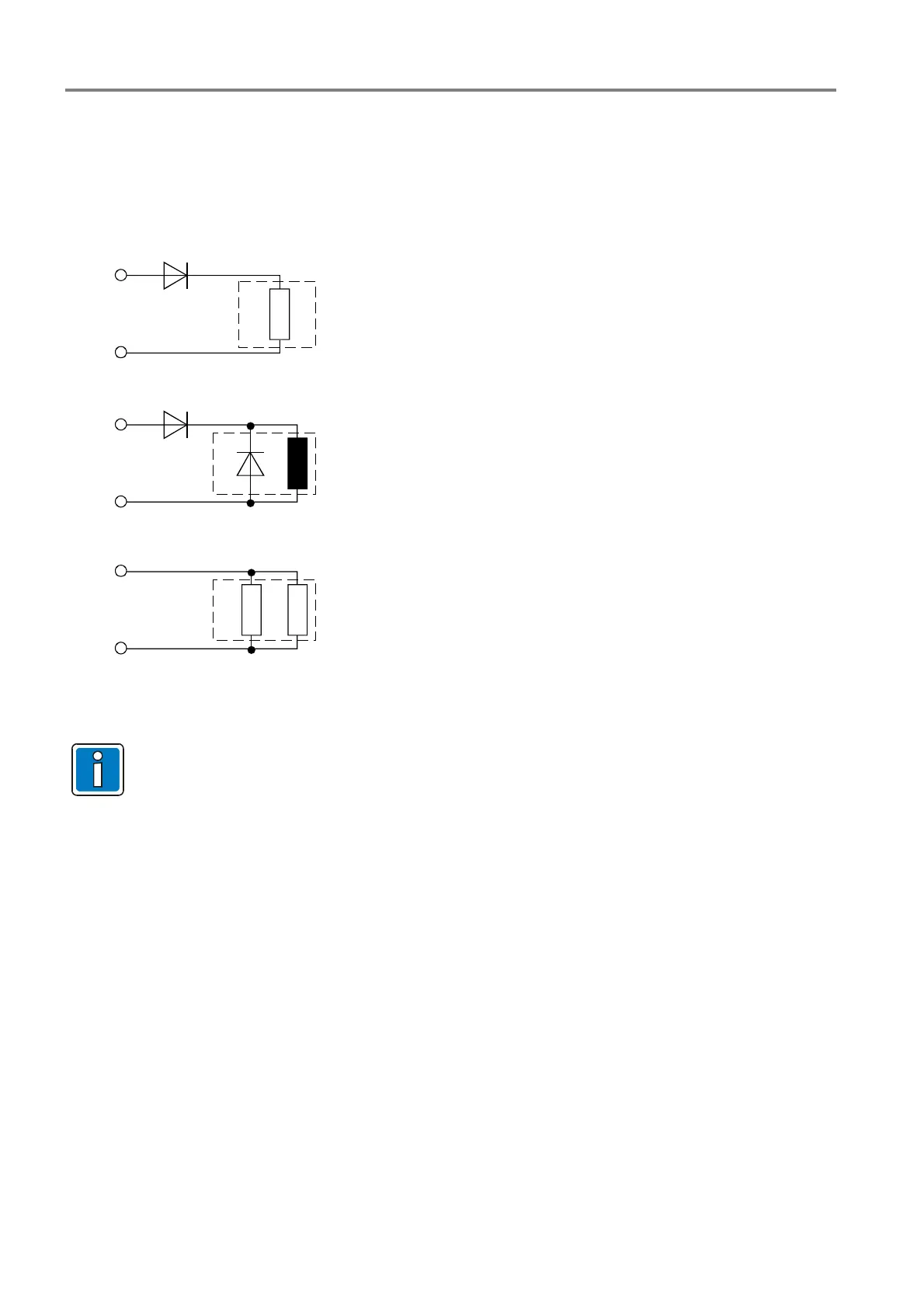
In case of an associated event, the relay is activated and the voltage (24 V DC) is switched to the external unit.
In the resting state, a voltage of approximately 1 V DC to 2 V DC must be present at the relay terminals during
the monitored mode.
This requires an external connection, depending on the application:
R
L
= low-resistance load R < 300 Ohm
D
1
= series diode BY251 (notice relays current max. 2 A)
L = inductive load
D
1
= series diode BY251
(notice relays current max. 2 A)
D
2
= recovery diode e.g. 1N4007 o.ä.
R
L
= high-resistance load > 2 kOhm
R = parallel resistor 2 kOhm
R
L
D
1
L
D
1
D
2
R
L
R
relay
+
-
+
-
+
-
relay
relay
Fig. 42: Positive-switching / monitoring mode (Schematic wiring)
Only silicon diodes type BY251 must be used for this application!
 Loading...


