Galaxy Dimension Installer Manual
2-6
Connecting Additional Telecom Apparatus
A secondary socket, allows additional telecom apparatus to be connected in series with the on-board telecom
module. Connect the PHONE terminals A and B on the PCB to the terminals on the secondary socket. See
Figure 2-5.
System Wiring (cont’d)
Line Monitoring
Under normal idle state conditions, the on-board Telecom Module monitors the PSTN line. The communica-
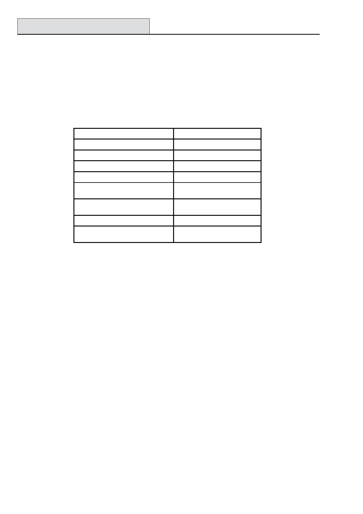
tion status is indicated by the state of the red LED (LED1) as shown in the following table:
Table 2-2. Comms Status
LED STATE INDICATION
LED OFF No d.c. supply
ON - 01s, OFF - 0.9s Normal Communication
Single pulse at end of call Normal Communication
Flashing at end of alarm call Failed Communication
On during alarm monitoring,
Remote Servicing and SMS
Normal Communication
Flickering during alarm monitoring,
Remote servicing and SMS
Poor Communication
Flashes in time with ringing signal Line Ringing
Pulses as each digit is dialled
Normal indication when
making call

 Loading...


