Galaxy Dimension Installer Manual
3-1
SECTION 3: PERIPHERALS
General
The following peripherals can be connected to the Galaxy Dimension panel:
All bus lines: Mk7 Keypad/Keyprox; TouchCenter; MAX
3
; Door Control Module (DCM); Remote Input
Output module (RIO); Power Supply Unit (PSU).
Bus line 1 only: Telecom; RS232; ISDN; Ethernet.
Wiring
Th following table shows the wiring between the Galaxy panel and the different peripherals.
RIOs
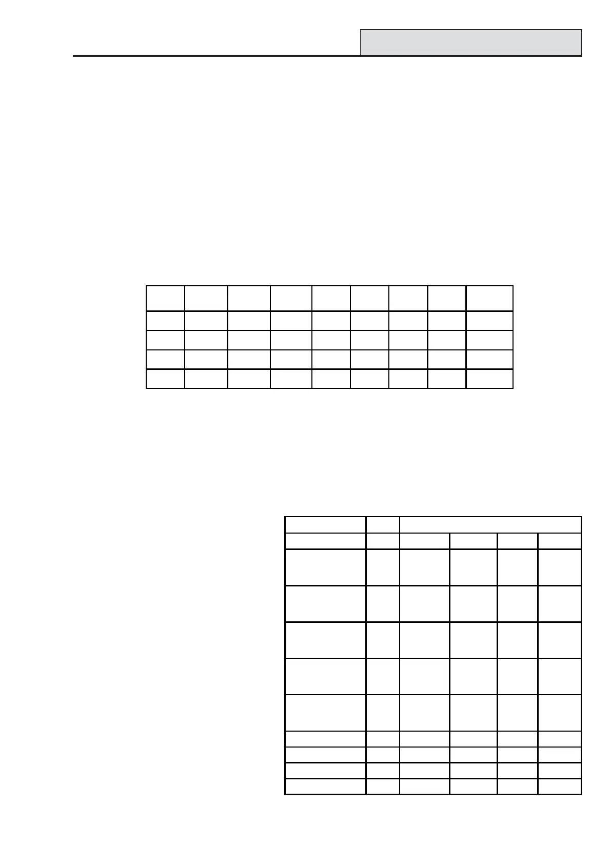
Table 3-1. Peripheral Wiring to Galaxy Panel
* Do not connect +12V terminals between panels and remote power supplies.
Configuring
New peripherals will be configured onto the system at system power up or on leaving programming mode.
Changes to peripheral addresses will only take effect when the peripheral is re-powered.
Addressing
The addresses on most peripherals is
set by either jumpers or a rotary
switch. These must be set before the
system is powered up. The table
opposite shows the available peripheral
addresses.
NOTES:
1 A single TouchCenter can be
fitted to each bus line.
2 If RIO 2 on-board is set to line 0
(dip switch 8), then the first
external RIO can use address 1
to give 8 extra zones where
needed.
Table 3-2. Galaxy Dimension Peripheral Addresses
Panel Keypad/-
Keyprox
Touch
Center
RIO/DCM PSU Telecom RS232 ISDN Ethernet
+12V + + + X* +12V +12V +12V +
GND - - - 0V - - GND -
A A G A AAAA A
B B Y B BBBB B
Valid Addresses
Peripheral Line GD-48 GD-96 GD-264 GD-520
Mk7 Keypad 1
2
3-4
0-2, B-F
-
-
0-2, B-F
0-2, B-F
-
0-2, B-F
0-6, F
-
0-2, B-F
0-6, F
0-6, F
Mk7 Keyprox 1
2
3-4
0-2
-
-
0-2
0-3
-
0-2
0-3
-
0-2
0-6
0-6
To u c h C e n t e r
1
1
2
3-4
0-2
-
-
0-2
0-3
-
0-2
0-3
-
02
0-6
0-6
RIO/PSU 1
2
3-4
2-5
-
-
2
2
-5
0-5
-
2
2
-9, A-F
0-9, A-F
-
2
2
-9, A-F
0-9, A-F
0-9, A-F
MAX/DCM Reader 1
2
3-4
0-3
-
-
0-3
0-3
-
0-3
0-3
-
0-7
0-7
0-7
Telecom 1 (E) (E) (E) (E)
RS232 1 (D) (D) (D) (D)
ISDN 1 (C) (C) (C) (C)
Ethernet 1 (B) (B) (B) (B)

 Loading...


