Galaxy Dimension Installer Manual
4-2
Addressing
Addresses are set by means of a rotary switch on the PCB. Each keypad must be assigned a unique address
for its line.
It is possible to add additional keypads at any unused comms module addresses (B, C, D and E) as detailed
in the following NOTE. These must be standard keypads. An engineer keypad can also be used at address F.
NOTE: On Line 1, keypad addresses B, C, D and E are not available if the Ethernet,
ISDN, RS232 or Telecom modules respectively are fitted.
Keypad/KeyProx Installation Procedure
1. To attach the keypad to the wall, the back plate must first be removed from the front plate. To do this,
insert a suitable tool into both openings at the bottom of the keypad and turn the tool gently.
CAUTION: When the keypad is separated make sure that the anti-static precautions are taken
with the keypad pcb to avoid damage from esd (electro static discharge).
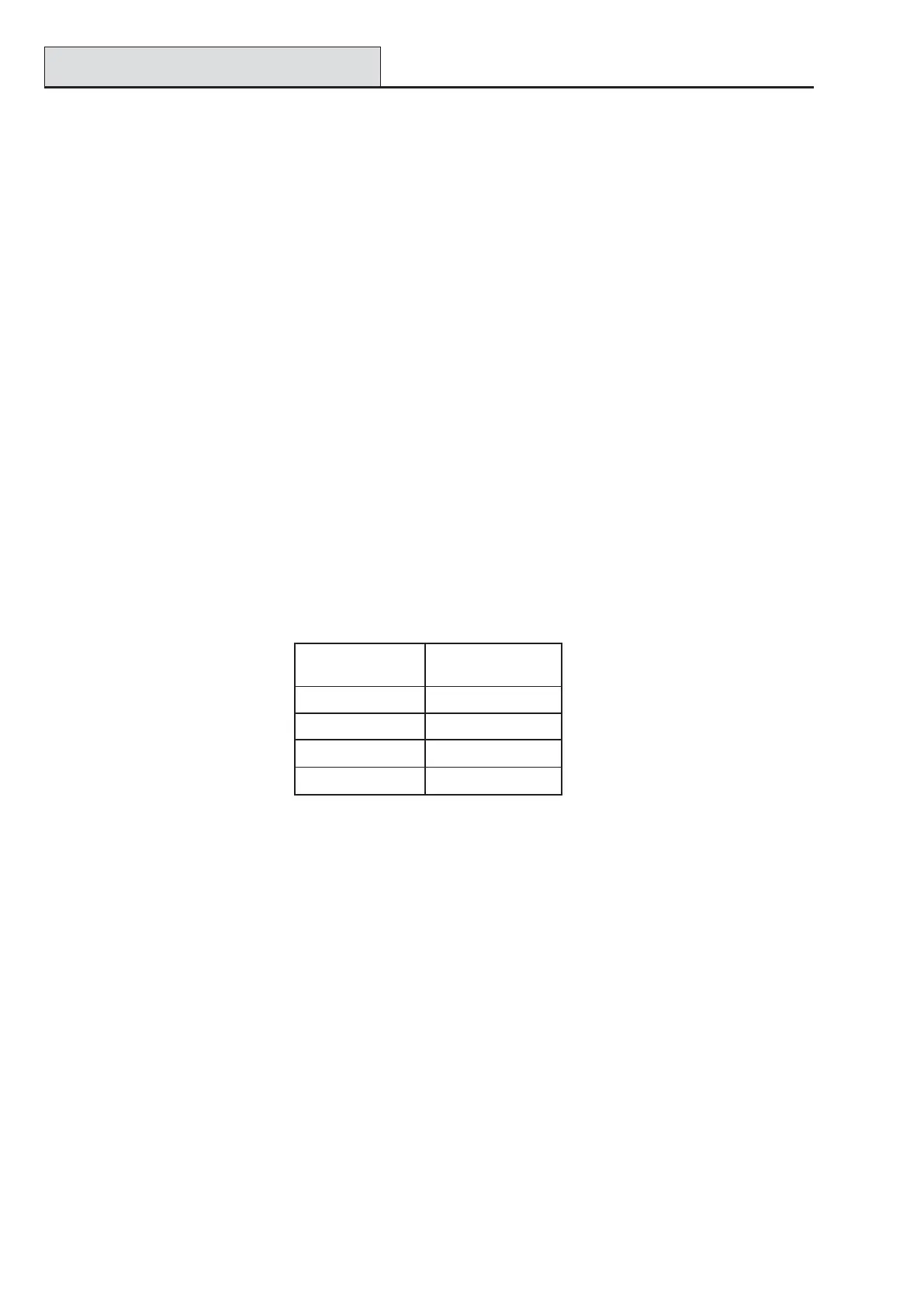
Connections to the terminals are:
2. Use the backplate as a template, then mark the locations for the three attachment screws in the
required position.
3. If it is a new installation, use the keyhole slot at the top of the backplate and the two elongated
holes at the bottom. If replacing an existing Mk3 keypad with a Mk7 keypad, use the keyhole
slot at the top of the backplate and the two knockout holes at the bottom. This means that you
can use the existing holes in the wall, whist keeping the backplate in the same position.
4. If you are using a wall-run cable for the keypad (A, B, +12V, 0V) position the cable behind the
back plate in the cable channels provided. The cable can be run in from either the top or the
bottom of the back plate. Use a sharp tool to remove the plastic from the top or the bottom of the
cable guides on the back plate skirting.
CAUTION: Use of any screws other than No. 6 Pan-head can damage the keypad
mouldings.
5. Make sure that the keypad wiring is fed through the large opening on the keypad backplate, then
position the keypad base on the wall and attach it securely with the three No. 6 Pan-head screws.
Keypad Installation
Wiring the Keypad/KeyProx
A 16-way rotary address switch is used to address Galaxy LCD keypads. The address switch assigns a
hexadecimal address value to the keypad.
NOTE: Any change to the keypad address must be made when the power is disconnected from the
keypad.
rotcennoC
slanimreT
sdapyeKyxalaG
A lenapotenilA
B lenapotenilB
+ tupni.c.dV21
– V0
Table 4-2. Keypad/keyProx Terminal Connections

 Loading...


