Galaxy Dimension Installer Manual
3-15
Audio Control (cont’d)
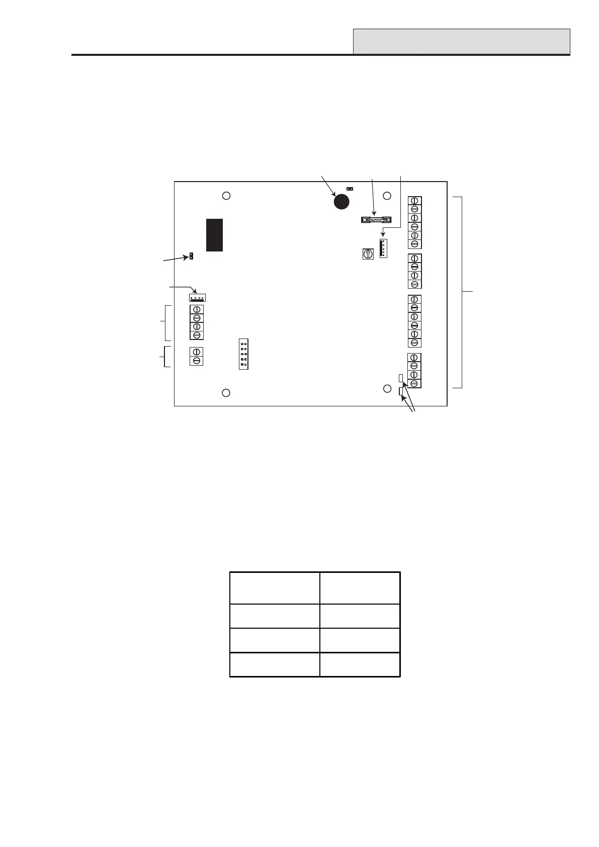
MUX Module
The MUX Module allows four additional audio channels to be connected. It is connected to the RS485
Audio Bus and acts as a slave module to the Audio Interface.
Each audio channel can have three standard speaker-mic devices such as the TP800 connected.
Figure 3-8. Mux Module PCB
Addressing
The Mux Module must be given a unique address before it is connected to a power supply. This address is
selected using the 16-way Rotary address Switch (SW1). Valid addresses are 0 - 7.
Connecting the MUX Module to the Audio Interface
The MUX Module is connected to the Audio Interface via the RS485 Audio Bus. The following table shows
the connections.
Table 3-10. Mux Connections
Connecting Microphones and Speakers
The MUX module is connected to microphones and speakers as per the Audio Interface. See table 3-8.
NOTE: The MUX module can either be supplied with DC power from the Audio Interface or from a local
Power Supply Unit (eg Smart). See Figure 3-8.
Debug Header
LK4
LK3
CMD 4
TMP 4
SPK 4
MIC 4
GND
SPARE
AUDIO
A
B
PL6
Rotary
Address
Switch
GND
+4.5V
CMD 3
TMP 3
SPK 3
MIC 3
CMD 2
TMP 2
SPK 2
MIC 3
GND
+4.5V
CMD 1
TMP 1
SPK 1
MIC 1
F1
PL2
Jumper lead
RS485
termination
Engineer Header
Audio Bus
RS485
Audio
Off-wall Tamper
microswitch
Fuse for
+4.5V
Audi Channel
Terminals (4)
Audio Expansion
Header (for future
product development)
Diagnostic
LED's
SW3
SW1
+12V
GND
DC Supply
from Master
or from
local PSU
Audio Interface
RS485 Bus
MUX RS485
Audio Bus
GND GND
Audio A Audio A
Audio B Audio B

 Loading...


