Galaxy Dimension Installer Manual
3-14
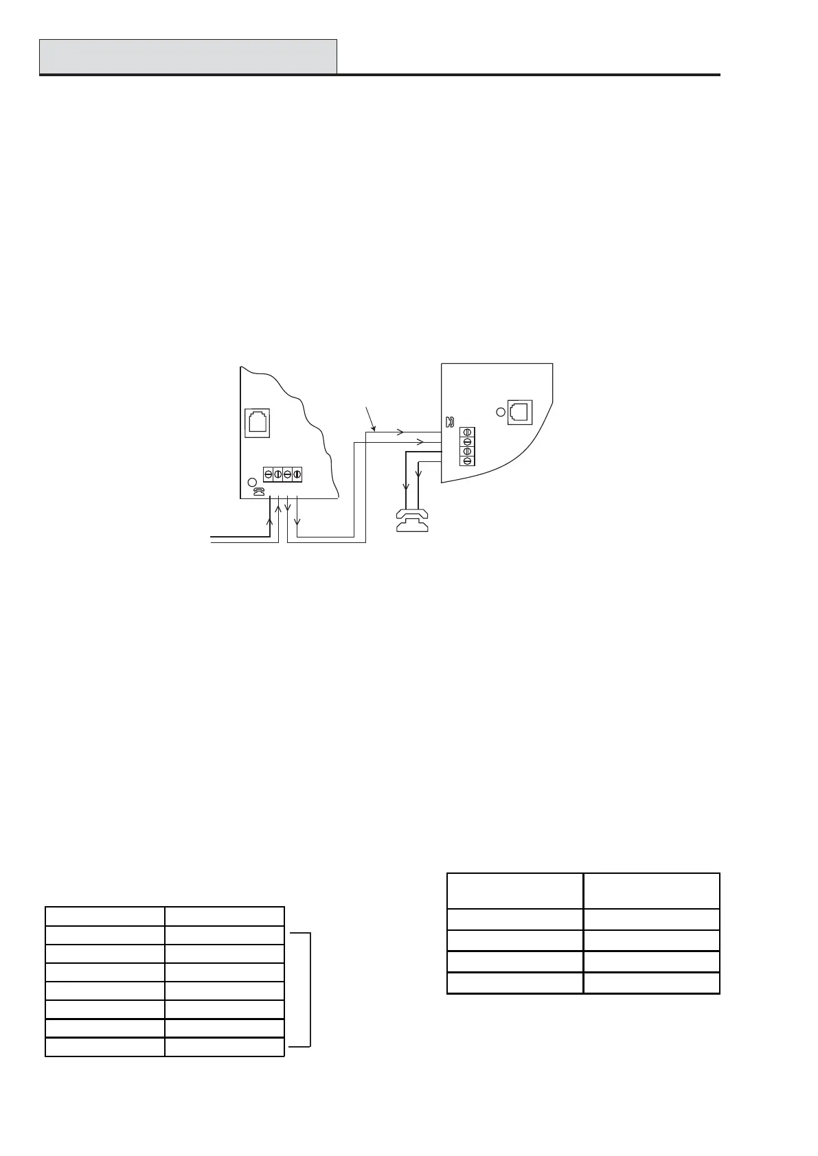
Connecting the Audio Interface Module to the PSTN
The Audio Interface Module must be connected to the Galaxy panel PCB as in the following diagram.
Audio Control (cont’d)
TP800/TP2-800GY Connection
The following table details the terminal connections
of the TP800 speaker unit to the Audio Interface:
Figure 3-7. Audio Interface connected to PSTN
Connecting Microphones and Speakers
The Audio channels can work with most line-level audio equipment. Microphones must have a pre-amplifier
that delivers audio or can deliver audio at line level (3V peak to peak). The audio card can transmit audio to
speakers with their own amplifier which accepts line level signals. Please see any instructions with the Micro-
phone device regarding the adjustment of sensitivity. The Galaxy Audio system can be used with the following
Honeywell audio devices:
TP800/TP2-800GY: Speaker and Microphone unit
IS215TCE-MIC: PIR detector with built-in microphone
DT7450-MIC: Dual Tech detector with built-in microphone
Link AP to VS-
to complete
tamper circuit
Addressing
The AudioInterface has a fixed module address.
Mounting
the Audio Interface Module can be mounted in two ways:
• above the control panel PCB using a specially designed mounting plate.
• inside a standard RIO box separate from the control panel.
Table 3-8. TP800/TP2-800GY
Connections to Audio Interface
IS215TCE-MIC/DT7450-MIC
Connection
Table 3-9. Detector Connections to
Audio Interface
PHONE
LINE
A
B
AB
Galaxy Panel PCB
PHONE
LINE
A
B
AB
Audio Interface PCB
Extension Phone
Incoming
PSTN Line
30 metres maximum from
panel to Audio Interface
Audio Interface TP800/TP2-800GY
GND VS-
+4.5V VS+
CMD CMD
SPK RML
MIC ECOUT
TMP AP
AP
Audio Interface IS215TCE-MIC/DT7450-
MIC
GND -
12V +
MIC M
GRD G

 Loading...


