Galaxy Dimension Installer Manual
2-14
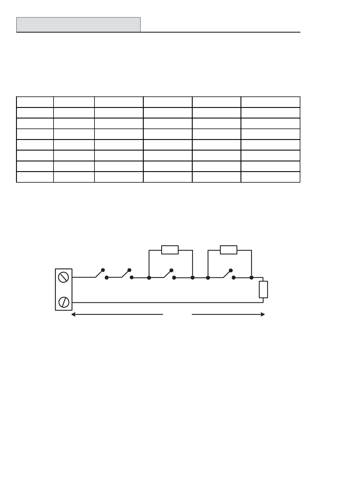
Figure 2-12. Option 10 - End of Line Zone/Detector wiring
Option 10 - 1k Fault End-Of-Line
The wiring in Figure 2-12 should be used if the mode is end-of-line. Fault and mask indications can only be
signalled if the detector has seperate fault and mask indications.
Zone
Tamper N/C
1k
100 m
Alarm N/C
Fault N/C
3k
12k
Anti-Mask N/C
When this wiring mode is employed, only one detector which can report fault conditions should be connected
to the zone. A maximum of two detectors or contacts of any type should be connected to a zone when this
mode is selected. It is recommended that zone cable lengths are kept below 100m in this configuration.
NOTE: The recommended maximum cable run from a zone to a detector is 500 metres in all other configu-
rations.
Table 2-8. End of Line Zone Resistance and Conditions
Wiring Zones (cont’d)
When this wiring mode is employed, only one detector which can report fault conditions should be connected
to the zone. A maximum of two detectors or contacts of any type should be connected to a zone when this
mode is selected. It is recommended that zone cable lengths are kept below 100m in this configuration.
NOTE: The recommended maximum cable run from a zone to a detector is 500 metres in all other configu-
rations.
Option 02 - 1k Option 04 - 2k2 Option 06 - 4k7 Option 08 - 5k6 Option 10 -1k Fault
Tamper S/C 0 - 800 0 - 1800 0 - 3700 0 - 1400 0 - 800
Low Res 800 - 900 1800 - 2000 3700 - 4200 1400 - 2800 800 - 900
Normal 900 - 1200 2000 - 2500 4200 - 5500 2800 - 8400 900 - 1200
High Res 1200 - 1300 2500 - 2700 5500 - 6500 8400 - 9800 1200 - 1300
Fault - - - - 1300 - 4500
Masked 1300 - 12000 2700 - 12000 6500 - 19000 9800 - 19000 4500 - 19000
Open 12000 - infinity 12000 - infinity 19000 - infinity 19000 - infinity 19000 - infinity

 Loading...


