Galaxy Dimension Installer Manual
5-5
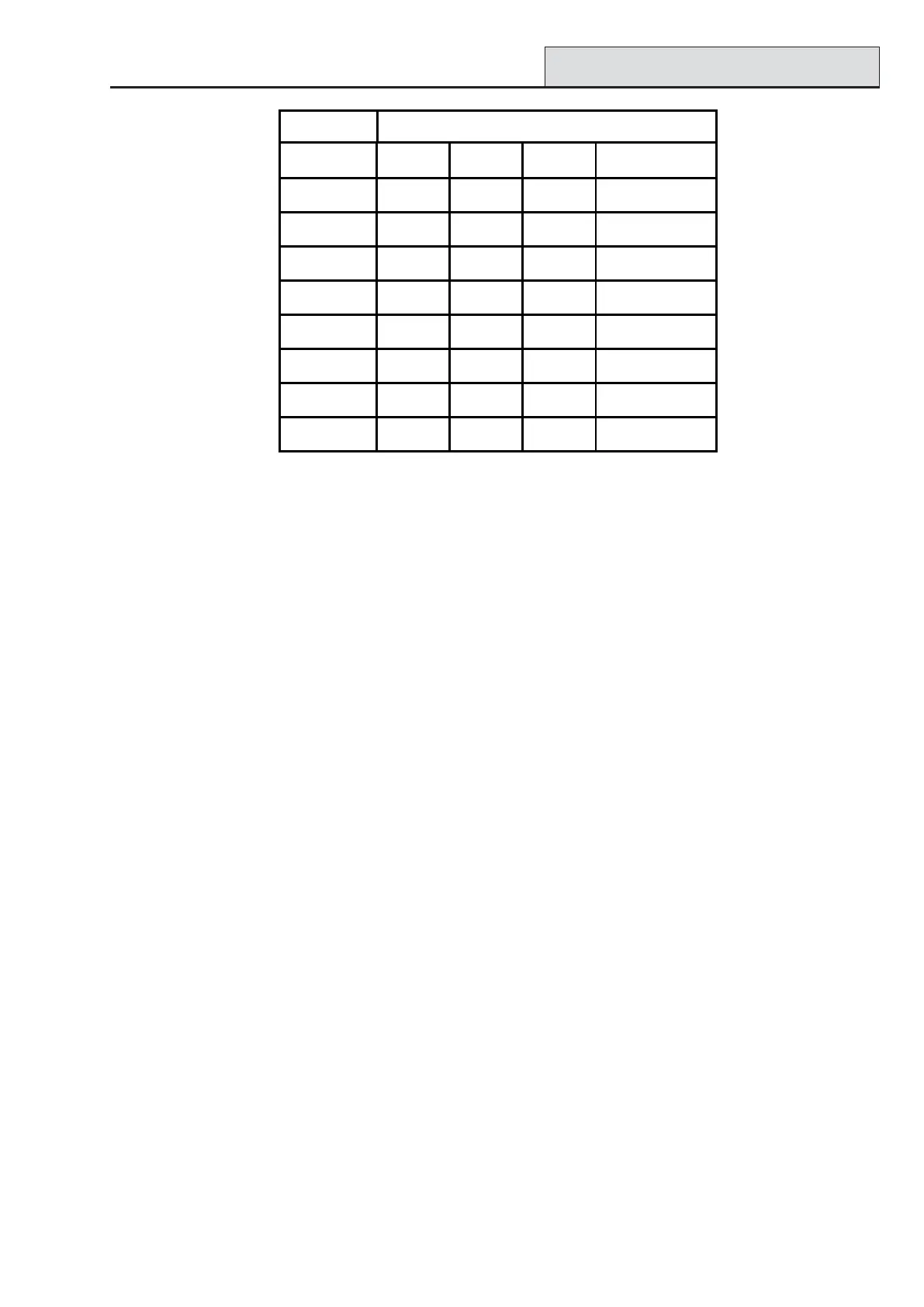
Table 5-1. DIP Switch Addressing
Connecting the DCM to Galaxy System
The DCM must be wired to the Galaxy RS485 (AB) line in parallel (daisy-chain configuration). The DCM
requires 12V d.c. This can be supplied from the control panel power supply or from the Power RIO when
mounted inside the Power RIO box.
See Figure 5-1 for a diagram of the connections.
NOTE: If the DCM is the last module on the line, connect a 680 Ω EOL resistor across the A and B
terminals.
Configuring the DCM
The added DCM is configured into the system on power up of the control panel or when exiting from engineer
mode. The flash rate of the green comms LED (LED1) on the DCM indicates the status of the communication
with the control panel. A short flash once per second indicates good communications.
LED 2 when lit indicates that there is power to the DCM.
Access Control (cont’d)
Switch
Address 1 2 3 4-8
0 OFF OFF OFF OFF
1 ON OFF OFF OFF
2 OFF ON OFF OFF
3ONONOFFOFF
4 OFF OFF ON OFF
5ONOFFONOFF
6 OFF ON ON OFF
7 ONONON OFF

 Loading...


