Honeywell Sensing and Control 39
SC 2000, SC2001, SC3004
Rev. G, 008-0608-00
Chapter 11 AC/AC-LVDT Input
Channel
11.1 Features
The ac/ac-LVDT Input channel provides an ac excitation voltage
to and accepts ac signals from LVDT (Linear Variable Differential
Transformer) transducers. These signals are digitized, converted
into engineering units, and placed into the track, peak and valley
data values of the channel. Setup and calibration of the channel
are made manually through the SETUP mode.
The analog-to-digital converter features adjustable digital, low-
pass filtering, 12- to 18-bit resolution (depending on the filter
setting) and has several different input ranges. These many input
rangesallow±25,000countresolution(attheslowestlterset-
ting) for a wide variety of LVDT outputs.
The ac/ac-LVDT Input channel is calibrated to the transducer by
using known-displacement calibration.
Two rear panel control inputs can be field-configured for such
functions as remote tare, disabling peak/valley detection and
clearing the peak/valley values. A standard voltage or optional
current digital-to-analog output is also provided.
NOTICE
To use a dc/dc LVDT with an SC instrument, use a High-Level
Input channel instead of an ac/ac-LVDT Input channel.
11.2 Wiring
Connect your transducer to an ac/ac-LVDT Input channel by
wiring it to the 12-pin connector of that channel. The Customer In-
formation Sheet that shipped with the instrument describes which
cards are installed in each channel. The pin-out for this connector
is shown on the following table.
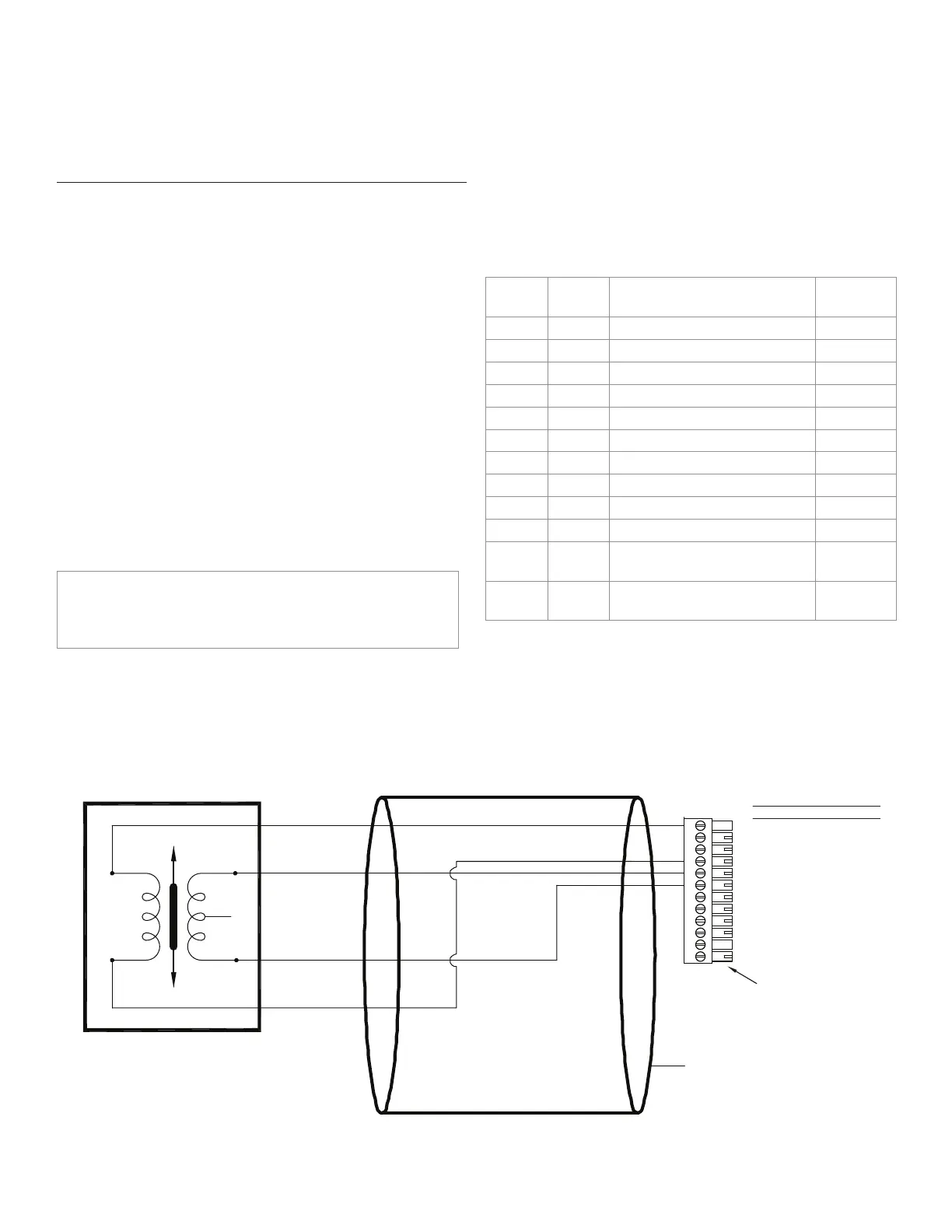
Table 11-1: ac/ac-LVDT Input Channel Pin Connections
Pin Label Function Reference
Pin
1 (top) +EXC (+)Excitation 10
2 N/C No connection
3 N/C No connection
4 -EXC (-)Excitation 10
5 +SIG (+)Signal 10
6 -SIG (-)Signal 10
7 +OUT Analog Output 8
8 -OUT Analog Return -
9 N/C No connection
10 DGND Digital Ground -
11 AUX1 Auxiliary Function 1 (connect
to pin 10 to activate)
10
11 (bot-
tom)
AUX2 Auxiliary Function 2 (connect
to pin 10 to activate)
10
The Analog Output and Analog Return pins are electrically iso-
lated from all other pins on the instrument.
Figure 11-1: Connection of Four- or Five-wire ac/ac-LVDT
1
2
3
4
5
6
7
8
9
10
11
12
(+)EXCITATION
N/C
N/C
(-)EXCITATION
(+)SIGNAL
(-)SIGNAL
(+)ANALOG OUTPUT
(-)ANALOG OUTPUT
N/C
DGND
AUX1
AUX2
DESIGNATION
PIN
CABLE SHIELD CONNECTION SCREW
(+)SUPPLY
SUPPLY RETURN
(+)OUTPUT
OUTPUT RETURN
AC-AC LVDT TRANSDUCER CABLE INSTRUMENT CONNECTIONS
(CONNECT TO CABLE SHIELD)
N/C
NOTE KEYED CONNECTOR

 Loading...


