Honeywell Sensing and Control 19
SC 2000, SC2001, SC3004
Rev. G, 008-0608-00
Chapter 6 System Menu
6.1 Overview
The System menu allows you to examine and change settings
that affect the chassis of the SC instrument. You can view the
internal software revision and the instrument’s configuration (i.e.
what types of cards are installed in each channel).
Detailed instructions on operating the SC instrument in the SET-
UP Menu mode can be found in “SETUP Menu mode” on page 7.
A diagram of all menus is located in the “Setup Menu Reference”
on page 77.
6.2 Menu Items
6.2.1 SOFTWARE REVISION Menu Item
This displays the software part number and revision that is resi-
dent in the Microprocessor Board of the SC instrument.
6.2.2 CONFIGURATION Sub-Menu
When selected, a sub-menu is displayed which lists all avail-
able channels in an SC Series instrument. By pressing [ENTER]
when a channel number is displayed, the card type installed in
that channel is shown. If a card is not installed in that channel,
the message “NOT INSTALLED” is shown. Press [ENTER] again to
return to the sub-menu listing of all channels.
6.2.3 DIAGNOSTICS Sub-Menu
This sub-menu allows exercising and monitoring of the System
connector’s output and input pins.
OUTPUT n, PIN nn Menu Items
These menus items are used to select an output pin to turn “on”
(connected to pin 19) or “off” (disconnected from pin 19). The
output pins are updated immediately.
INPUT TEST Menu Item
When this item is selected, the status of all four digital inputs are
continuously scanned and displayed. A “0” means that an input
is not connected to pin 19 (not asserted), and a “1” means that it
is connected (asserted). Press any button to exit this operation.
SCAN TIME Menu Item
When selected, this menu item displays the time, in seconds, that
it last took for the chassis to service all of the channels. In the
RUN mode, the chassis reads each channel’s track, peak and
valley value sequentially. After each channel has been serviced,
the limits are processed.
The value displayed is obtained from the last execution of the
RUN mode prior to entering the SETUP menu mode. If you enter
the SETUP mode immediately after power up, the display will
read “NOT AVAILABLE”.
6.2.4 INSTALL CHANNEL Menu Item
This menu item will add an Input, Output or Virtual channel as the
next highest channel number in the system.
NOTICE
Installing a channel will cause it to use the “default” or
“empty” configuration information for that channel. All other
channels are unaffected.
Any calibration data, SensoCode mathematics programs,
display setup, or other information for that channel will
be erased to default values.
Input or Output Channel Installation Procedure
Before installing an Input or Output card, make certain that you
know the “card type” (a two-digit hexadecimal number) of the
card you wish to install.
CAUTION
Use Electrostatic Discharge (ESD) precautions when unpack-
ing and handling circuit boards..
Failure to comply with these instructions may result in
product damage.
Use the following procedure to install an Input or Output card:
1. When the instrument is in the RUN mode, use the [ENTER]
button to change which channel the display is monitoring.
Note the highest channel number that is presently installed.
The new circuit card for the new channel will be installed as
the next channel number.
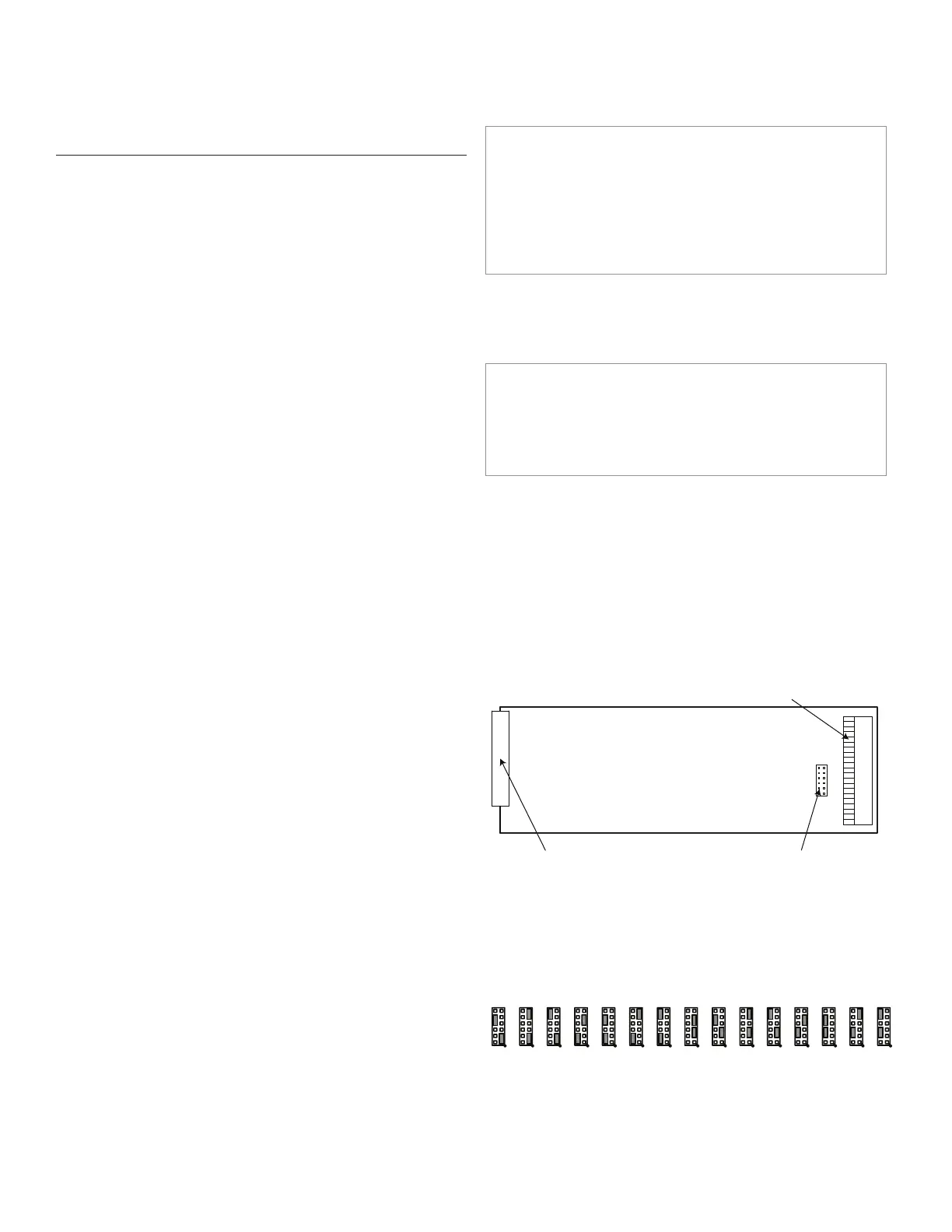
2. Examine the circuit card to be installed and orient it as
shown in Figure 6-1. On it you will find the address jumper
block.
Figure 6-1: Address Jumper Block Location
12-pin rear panel connector address jumpers
3. Change both address jumpers to match the next available
channel in the instrument according to the chart below. Do
not skip any channel numbers.
Figure 6-2: Address Jumper Settings (see next page for larger
view of settings)
0401 02 03 0705 06 0908 10 1211 13 14 15

 Loading...


