20 Honeywell Sensing and Control
Signal Conditioning, Self Calibrating Digital Indicators
Rev. G, 008-0608-00
Input Channels, Output Channels and Virtual Channels (such as
Mathematics Channels and Split Display Channels) all require an
unique address.
4. Turn the instrument off and remove the power cord from the
power source.
5. Find the “Case Removal” in Chapter 4 “Chassis Models” on
page 9 that matches the particular chassis model. Follow the
directions and remove the rear panel.
6. Locate an unused 42-pin SensoBus connector on the Sen-
soBus mother board and make certain that all of its pins are
not bent out of shape. It does not matter into which slot you
install the card as the addressing is implemented with the
address jumpers. However, it is most convenient to match
the card’s address with the channel numbers silk-screened
on the rear panel.
7. Install the card into an unused 42-pin SensoBus connector
on the SensoBus mother board. Make certain the card is fully
seated.
8. Replace the rear panel.
9. Re-connect the power cord to the power source. Turn the
instrument on.
10. Enter the SETUP menu mode, then select “SYSTEM MENU ->
INSTALL CHANNEL”. The instrument will then present a menu of
card types available for installation.
11. Use the [UP] and [DOWN] buttons to select the card type of
the card you wish to install. After you select the card type to
be installed, you are asked “ARE YOU SURE?”. To cancel this
operation, select “NO” or press the [EXIT] button. If “YES” is
selected, “WORKING...” is displayed and the installation will
commence.
12. If the installation was successful, “DONE” will be displayed. If
the installation failed, you will see one of the following mes-
sages:
• “SYSTEM IS FULL”: There are no unused channels available in
the instrument.
• “WON’T INSTALL”: The Output Relay card type you selected
to install does not match the next available set of Limits. For
example, the Limit 09-12 card type will not install unless the
Limit 05-08 card type has been installed.
• “ERROR 28 ON CH.xx”: The instrument could not communicate
with the card’s EEPROM memory. This is usually caused by
the address jumpers being set incorrectly or if the card is not
physically inside the chassis.
Virtual Channel Installation Procedure
Use the following procedure to install a Virtual Channel:
1. Enter the SETUP menu mode, then select “SYSTEM MENU ->
INSTALL CHANNEL”. The instrument will then present a menu of
card types available for installation.
2. Select the card type of the card you wish to install. After you
select the card type to be installed, you are asked “ARE YOU
SURE?”. To cancel this operation, select “NO” or press the
[EXIT] button. If “YES” is selected, “WORKING...” is displayed
an the installation will commence.
3. If the installation was successful, “DONE” will be displayed.
If the installation failed, you will see one of the following mes-
sages:
• “CAN’T INSTALL”: There is no more memory available for
Virtual channels.
• “SYSTEM IS FULL”: There are no unused channels available in
the instrument.
After installing a Mathematics Virtual channel, you must re-load
the SensoCode program into the channel with a computer run-
ning the “SensoCom Instrument Utility Software”. See “Mathemat-
ics Virtual Channel” on page 71 for more information.
6.2.5 DELETE CHANNEL Menu Item
This menu item will delete the last channel in the instrument.
Before deletion occurs, the number of the channel to be deleted
is displayed and you are asked “ARE YOU SURE”. To cancel this
operation, select “NO” or press the [EXIT] button. If “YES” is
selected, the last channel in the system will be deleted.
After a hardware channel has been deleted, you can safely
physically remove it from the chassis. See “Case Removal” on
page 11 for SC2000 instruments. See “Case Removal” on page
14 for SC3004 instruments.
NOTICE
Re-installing a deleted channel will erase all of its
configuration information!
6.2.6 DEFAULT CHANNEL Menu Item
This menu item will reset all settings for the channel you select to
their factory default values. Before the channel settings are reset,
you are asked “ARE YOU SURE?”. To cancel this operation, press
the [EXIT] button. If “YES” is selected, the channel’s settings will
be reset.
NOTICE
Defaulting a channel is an operation that cannot be undone.
All calibration information and other settings will be erased.
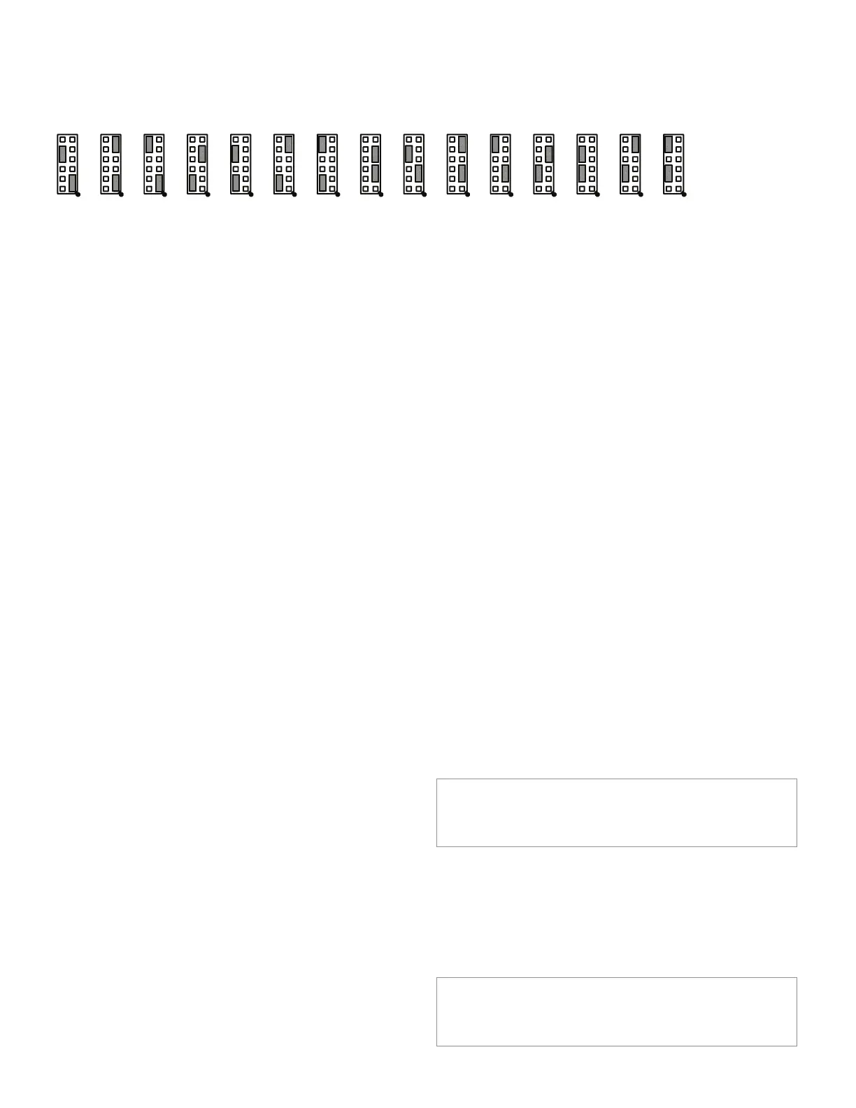
Figure 6-2: Address Jumper Settings (Larger View)
0401 02 03 0705 06 0908 10 1211 13 14 15

 Loading...


