68 Honeywell Sensing and Control
Signal Conditioning, Self Calibrating Digital Indicators
Rev. G, 008-0608-00
14.5.2 DIAGNOSTICS Sub-Menu
DAC FULL SCALE Menu Item
When this menu item is selected, the Analog Output of the chan-
nel is forced to its full-scale output, then DAC UPDATED is displayed.
This is useful when calibrating or trimming the readout connected
to the Analog Output.
AC ZERO SCALE Menu Item
When this menu item is selected, the Analog Output of the
channel is forced to its zero-scale output, then DAC UPDATED is
displayed. This is useful when calibrating or trimming the readout
connected to the Analog Output.
14.6 Analog Output Conguration
14.6.1 Identifying the Output Type
A DAC Output channel is available with one of two types of
digital-to-analog (DAC) outputs: voltage or current. You can de-
termine which type of output a channel has by one of three ways:
• Consultingtheinstrument’sCustomerInformationSheet
• ExaminingtheSYSTEM MENU -> CONFIGURATION -> CHANNEL nn
TYPE menu item where nn is the number of the channel. If the
channel’s type is VOLTAGE DAC, it has a voltage output. If the
channel’s type is CURRENT DAC, it has a current output.
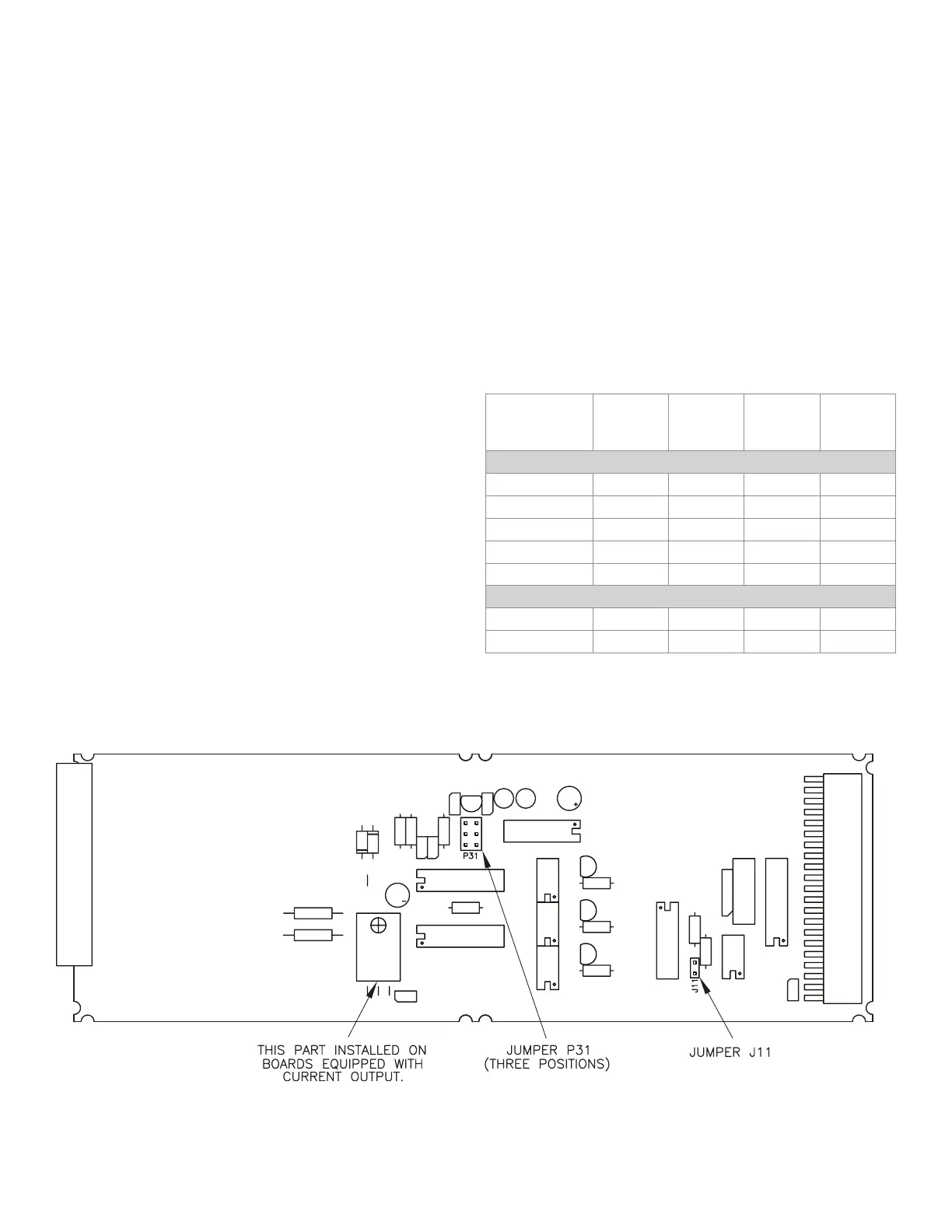
• Examiningthechannel’scircuitboardasshowninthegure
below.
14.6.2 Channel Menu Items
The Analog Output can be driven by any channel’s track, peak or
valley value.
See the “Channel Menu” section earlier in this chapter for a com-
plete listing of SETUP menu items available on the DAC. SETUP
sub-menu.
14.6.3 Output Selection
Jumpers located on the channel’s circuit board determine what
outputs are generated when the value selected to drive the Ana-
log Output (from the DAC. CHANNEL and DAC. SOURCE menu items)
equals the DAC. FULL SCALE and DAC. ZERO SCALE settings.
DAC. ZERO
SCALE
Output
DAC. FULL
SCALE
Output
P31
jumper
J11
jumper
CHANNELS WITH VOLTAGE OUTPUT
0 V to 5 V 2.5 Volts 5 Volts bottom open
±5V 0 Volts 5 Volts bottom closed
5 V 0 Volts 5 Volts top open
0 V to10 V 5 Volts 10 Volts middle open
±10V 0 Volts 10 Volts middle closed
CHANNELS WITH CURRENT OUTPUT
4 mA to 20 mA 4 mA 20 mA bottom closed
4 mA to 20 mA 12 mA 20 mA bottom open
Figure 14-1: Digital-to-Analog Output Jumper Locations

 Loading...


