Honeywell Sensing and Control 33
SC 2000, SC2001, SC3004
Rev. G, 008-0608-00
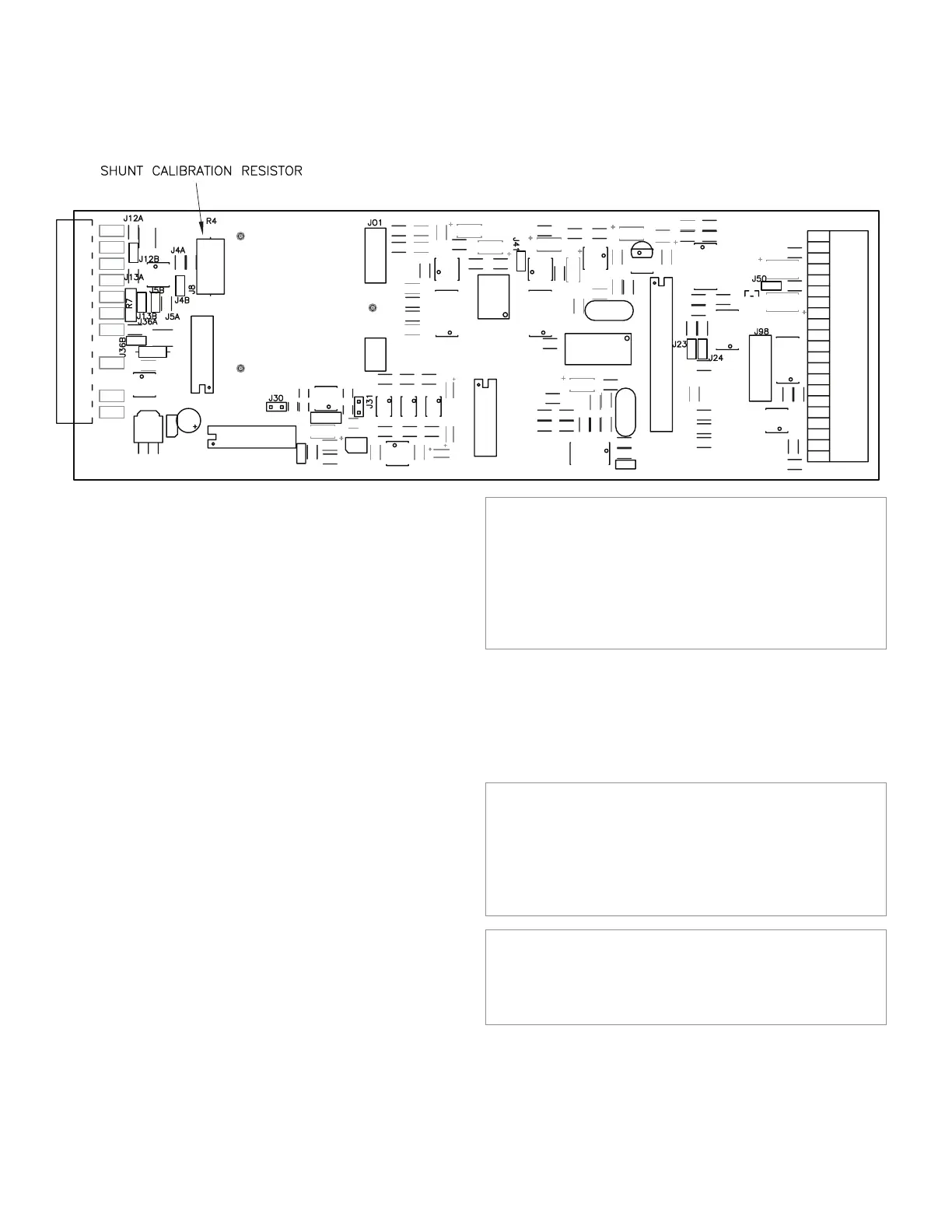
Figure 10-2: Shunt Calibration Resistor Location
KNOWN POINT x/y Menu Items
This enters the engineering units for the known-load calibration
points. These points must match the actual loads that you will
apply to the instrument during calibration. The number of calibra-
tions points depends on the CALIBRATION TYPE.
When using the 2-Point Known Load Calibration type, the follow-
ing menu items are available:
• “KNOWN POINT 1/2”: point 1 of 2, usually 0% of the transduc-
er’s full-scale capacity.
• “KNOWN POINT 2/2”: point 2 of 2, usually 100% of the trans-
ducer’s full-scale capacity.
When using the 3-Point Known Load Calibration type, the follow-
ing menu items are available:
• “KNOWN POINT 1/3”: point 1 of 3, usually 0% of the transduc-
er’s full-scale capacity.
• “KNOWN POINT 2/3”: point 2 of 3, usually 50% of the transduc-
er’s full-scale capacity.
• “KNOWN POINT 3/3”: point 3 of 3, usually 100% of the trans-
ducer’s full-scale capacity.
When using the 5-Point Known Load Calibration type, the follow-
ing menu items are available:
• “KNOWN POINT 1/5”: point 1 of 5, usually 0% of the transduc-
er’s full-scale capacity.
• “KNOWN POINT 2/5”: point 2 of 5, usually 25% of the transduc-
er’s full-scale capacity.
• “KNOWN POINT 3/5”: point 3 of 5, usually 50% of the transduc-
er’s full-scale capacity.
• “KNOWN POINT 4/5”: point 4 of 5, usually 75% of the transduc-
er’s full-scale capacity.
• “KNOWN POINT 5/5”: point 5 of 5, usually 100% of the trans-
ducer’s full-scale capacity.
NOTICE
To insure both correct operation of the transducer and appli-
cation of the load, the instrument expects the voltage applied
at each known-load point to be increasing. For example, the
load applied at Known-Load Point 2/2 must cause the trans-
ducer to produce a more positive voltage than at Known-Load
Point 1/2.
These menu items are only available with the Known-Load Cali-
bration types.
10.5.6 CALIBRATE Menu Item
This menu item performs a calibration according to what was en-
tered in the CALIBRATION TYPE and CALIBRATION DATA menu items.
NOTICE
Before performing a calibration, the transducer must be
connected to the instrument, the CALIBRATION TYPE must be
selected (see “CALIBRATION TYPE Menu Item” on page 31),
and the CALIBRATION DATA must be entered (see “CALIBRATION
DATA Sub-Menu” on page 32).
NOTICE
For maximum accuracy, allow at least twenty minutes of
warm-up with the excitation voltage applied to the transducer
before calibration.

 Loading...


