Honeywell Sensing and Control 49
SC 2000, SC2001, SC3004
Rev. G, 008-0608-00
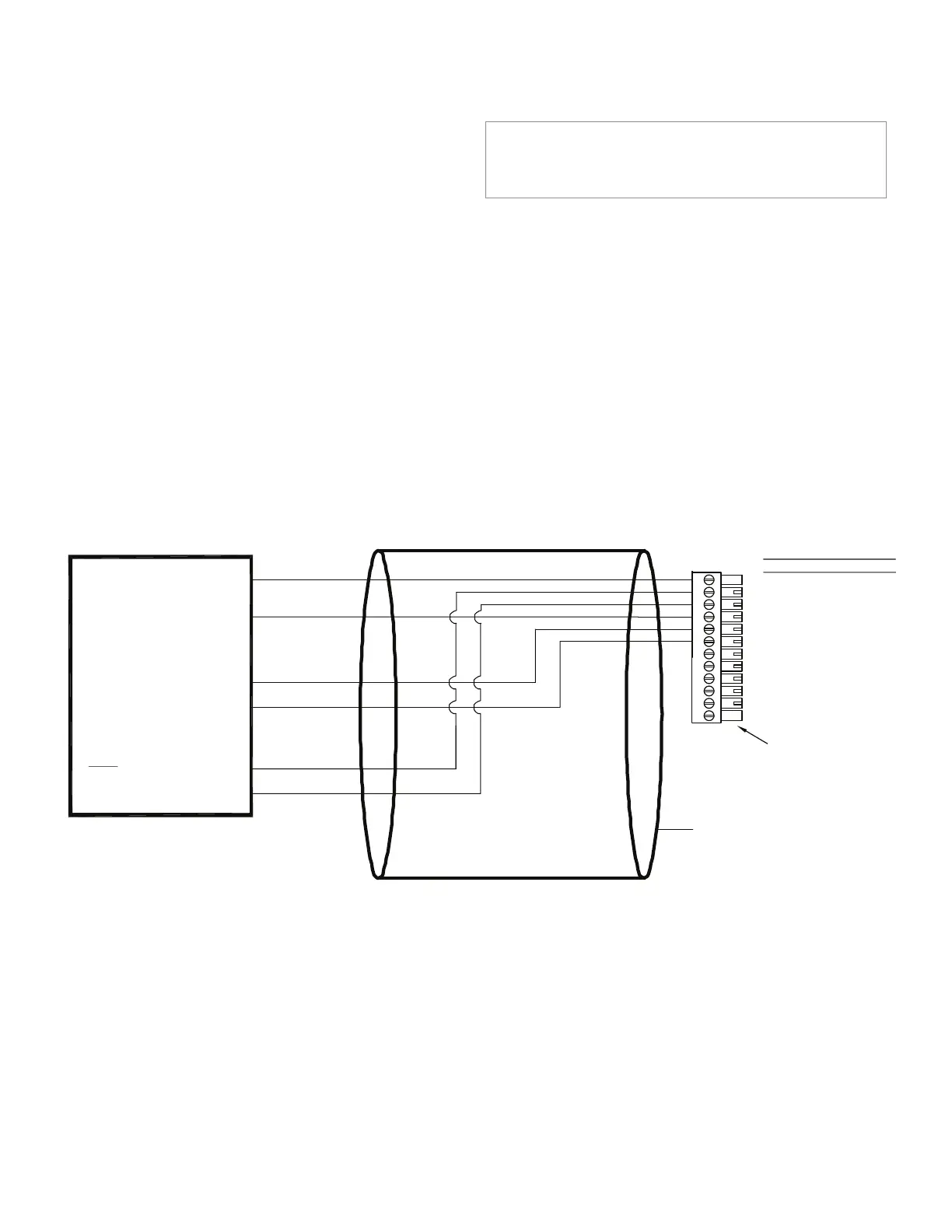
12.2.2 Bi-polar Voltage Ampliers
Use the following wiring diagram when connecting an amplified
transducer, in-line amplifier or dc-dc LVDT with a bi-polar volt-
age amplifier to a High-Level Input channel. Examples of such
devices include
• transducerswithOption2aorOption2binternalampliers
(with shunt cal)
• ModelsUBPorUBP-10UniversalIn-Lineampliers(with
shunt cal)
• ModelsJEC(replacesmodelMDL),JEC-AG(replacesmodel
DLA), JEC-C (replaces model MDLC), DW7U, DW7C and
DW7S dc-dc LVDTs (no shunt cal)
Figure 12-1: “Bi-polar Voltage Amp” Connection to High-Level Input Channel
NOTICE
See “Low Voltage dc-dc LVDTs” on page 55 for information on
wiring Model DLB, DLE and DLF low-voltage dc-dc LVDTs.
The High-Level Input channel’s Configuration Jumpers must be
set as follows for proper operation. See “Excitation and Signal
Jumpers” on page 56.
• (+)Excitationsupply:“+15Vdc”
• (-)Excitationsupply:“-15Vdc”
• Signaltype:“voltage”
• Signalreference:“singleended”
1
2
3
4
5
6
7
8
9
10
11
12
(+)EXCITATION
SHUNT CAL 1
SHUNT CAL 2
(-)EXCITATION
(+)SIGNAL
(-)SIGNAL
(+)ANALOG OUTPUT
(-)ANALOG OUTPUT
N/C
DGND
AUX1
AUX2
DESIGNATION
PIN
CABLE SHIELD CONNECTION SCREW
(+)SUPPLY
SHUNT CAL 1
(+)OUTPUT
(-)OUTPUT
IN-LINE AMPLIFIER
CABLE INSTRUMENT CONNECTIONS
(CONNECT TO CABLE SHIELD)
OR
(-)SUPPLY
SHUNT CAL 2
NOTE: SHUNT CALIBRATION
NOT AVAILABLE ON ALL
DEVICES.
SUPPLY
BI-POLAR POWER
VOLTAGE OUTPUT,
DEVICE WITH
NOTE KEYED CONNECTOR
+15V
-15V

 Loading...


