Honeywell Sensing and Control 65
SC 2000, SC2001, SC3004
Rev. G, 008-0608-00
Chapter 13 Relay Output Channel
13.1 Features
13.1.1 First Channel Installed
The first Relay Output channel installed in an instrument supple-
ments the standard four limits (Limit 1, Limit 2, Limit 3 and Limit
4) . Its four, dry contact relay outputs will mirror the Limit Outputs
pins of the System connector.
In the SYSTEM -> CONFIGURATION sub-menu, channels of this type
are identified as LIMIT 01-04.
13.1.2 Second Channel Installed
The second Relay Output channel installed in an instrument adds
another four limits to the instrument (Limit 5, Limit 6, Limit 7 and
Limit 8). Its relay outputs show the status of these limits.
In the SYSTEM -> CONFIGURATION sub-menu, channels of this type
are identified as LIMIT 05-08.
13.1.3 Third Channel Installed
The third Relay Output channel installed in an instrument adds
another four limits to the instrument (Limit 9, Limit 10, Limit 11 and
Limit 12). Its relay outputs show the status of these limits.
In the SYSTEM -> CONFIGURATION sub-menu, channels of this type
are identified as LIMIT 09-12.
13.1.4 Fourth Channel Installed
The fourth Relay Output channel installed in an instrument adds
another four limits to the instrument (Limit 13, Limit 14, Limit 15
and Limit 16). Its relay outputs show the status of these limits.
In the SYSTEM -> CONFIGURATION sub-menu, channels of this type
are identified as LIMIT 13-16.
13.2 Wiring
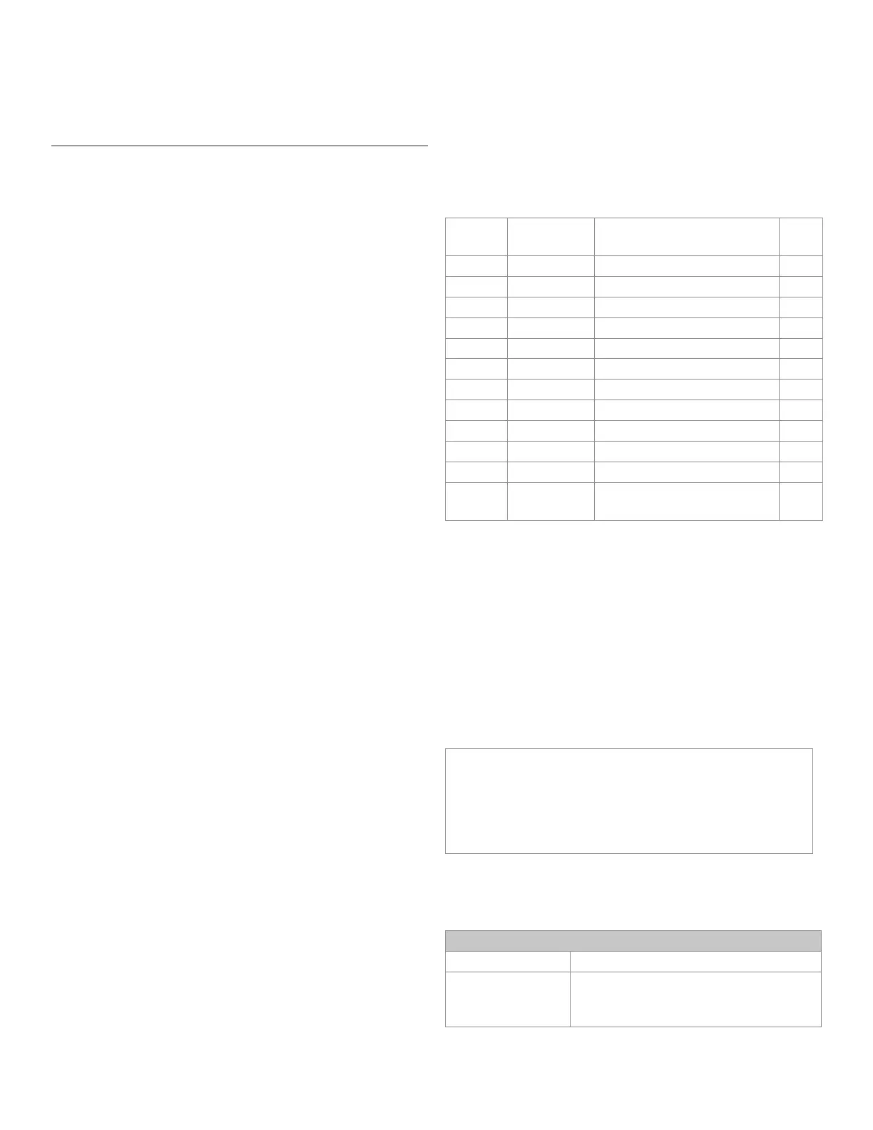
The pin-out for the Relay Output channel’s 12-pin connector is
shown in the following table.
Table 13-1 Relay Output Channel Pin Connections
Pin Label Function Ref.
Pin
1 (top) RELAY1 NC Relay 1 normally closed 2
2 RELAY1 C Relay 1 common -
3 RELAY1 NO Relay 1 normally open 2
4 RELAY2 NC Relay 2 normally closed 5
5 RELAY2 C Relay 2 common -
6 RELAY2 NO Relay 2 normally open 5
7 RELAY3 NC Relay 3 normally closed 8
8 RELAY3 C Relay 3 common -
9 RELAY3 NO Relay 3 normally open 8
10 RELAY4 NC Relay 4 normally closed 11
11 RELAY4 C Relay 4 common -
12
(bottom)
RELAY4 NO Relay 4 normally open 11
13.3 Setup Procedure
If you are not familiar with operating the instrument in the SETUP
menu mode, see “SETUP Menu mode” on page 7. A listing of all
menu item is given in “Setup Menu Reference” on page 77.
• Step1:Wiretothechannel’sconnector.
See the “Wiring” section earlier in this chapter for details.
• Step2:UsetheappropriateLimitMenutosetupthelimits.
See “Limits” on page 24 for information about limits.
NOTICE
A SensoCode program running on a Mathematics Virtual
Channel may override the default behavior of the relay out-
puts. Consult the Customer Information Sheet included with
your instrument for details.
13.4 Specications
RELAY OUTPUT
Quantity and Type 4 form C
Contact rating 0.5 A @ 50 Vac max. (consult factory for
125 Vac max. operation) 1 A @ 30 Vdc
max.

 Loading...


