28 Honeywell Sensing and Control
Signal Conditioning, Self Calibrating Digital Indicators
Rev. G, 008-0608-00
10.3 Calibration Procedure
If you are not familiar with operating the instrument in the SETUP
menu mode, see “SETUP Menu mode” on page 7. A listing of all
menu items is given in “Setup Menu Reference” on page 77.
• Step1:Wirethetransducertothechannel’sconnector.
See “Wiring” on page 27 for details.
• Step2:EntertheCALIBRATION TYPE.
There are three methods that can be used to calibrate the
transducer to the Input Channel. Each has advantages and
disadvantages as described in “CALIBRATION TYPE Menu
Item” on page 31. It is important to know your application in
order to select the appropriate calibration type.
• Step3:EntertheCALIBRATION DATA.
- If your transducer has Signature Calibration, you don’t
need to enter these values as they are entered automatically.
- If your transducer was ordered and shipped along with
the instrument, you don’t need to enter these values as they
have been entered at the factory.
- Otherwise, consult the Certificate of Calibration for the
transducer when entering information in the CALIBRATION
DATA sub-menu.
• Step4:Performthecalibration.
Otherwise, use the CALIBRATE menu item to start the calibra-
tion process. You will be prompted to apply loads to the
transducer as required.
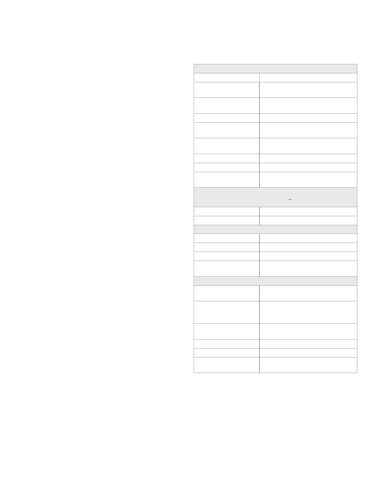
10.4 Specications
TRANSDUCER INPUT
Transducer type full-bridge, strain gage
Excitation voltage 5 Vdc or 10 Vdc, short circuit pro-
tected with sensing
Transducer full-scale
output
0.5 to 11.0 mV/V @ 5V excitation
0.5 to 5.5 mV/V @ 10 V excitation
Amplifier gain selection automatic
Calibration type shunt, mV/V or 2-, 3- or 5-point
known load
Differential Input Volt-
age
±55mV(max.)
A/D Converter 24-bit Sigma-Delta
Low-pass filter digital, 24-tap FIR
Resolution and Fre-
quency Response
see “FREQ. RESPONSE Menu Item”
on page 29
INSTRUMENT-ONLY ACCURACY
(Sense wires used; frequency response setting <16 Hz; Linearity, repeatability,
and hysteresis)
mV/V calibration ±0.1%FS
Known-load calibration ±0.01%FS
AUXILLARY INPUTS
Quantity 2
Type momentary contact closure
Response time < 5 ms
Field-selectable func-
tions
tare on, tare off, peak/valley clear,
peak/valley hold, track hold
ANALOG OUTPUTS
Output voltage range 5,±5,10or±10Vdc
(field selectable)
Output current range
(optional current output
channels)
4 mA to 20 mA
Source any channel’s track, peak, or valley
value
Isolation 500 V
Resolution 13 bits
Frequency response same as input when driven by the
same channel’s tracking data

 Loading...


