Honeywell Sensing and Control 55
SC 2000, SC2001, SC3004
Rev. G, 008-0608-00
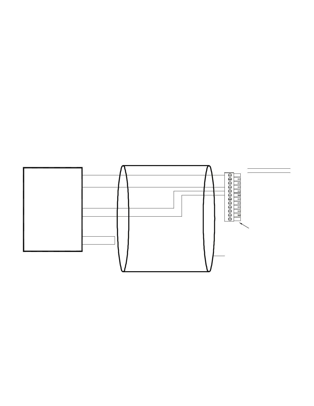
12.2.8 Low Voltage dc-dc LVDTs
Use the following wiring diagram when connecting a low-voltage
dc-dc LVDT to a High-Level Input channel. Examples of such
devices include
• ModelsDLB,DLEandDLFdc-dcLVDTs
The High-Level Input channel’s Configuration Jumpers must be
set as follows for proper operation. See “Excitation and Signal
Jumpers” on page 56.
• (+)Excitationsupply:“+12Vdc”
• (-)Excitationsupply:“GND”
• Signaltype:“voltage”
• Signalreference:“singleended”
Figure 12-7: “Low Voltage” dc-dc LVDT Connection to High-Level Input Channel
1
2
3
4
5
6
7
8
9
10
11
12
(+)EXCITATION
SHUNT CAL 1
SHUNT CAL 2
(-)EXCITATION
(+)SIGNAL
(-)SIGNAL
(+)ANALOG OUTPUT
(-)ANALOG OUTPUT
N/C
DGND
AUX1
AUX2
DESIGNATION
PIN
CABLE SHIELD CONNECTION SCREW
UNREGULATED
+5V REG. INPUT
(+)OUTPUT
OUTPUT RETURN
DC-DC LVDT
CABLE INSTRUMENT CONNECTIONS
(CONNECT TO CABLE SHIELD)
LOW-VOLTAGE
SUPPLY COMMON
+5V REG. OUTPUT
NOTE KEYED CONNECTOR
+12V
0V

 Loading...


