12 Honeywell Sensing and Control
Signal Conditioning, Self Calibrating Digital Indicators
Rev. G, 008-0608-00
4.3.7 Internal Arrangement
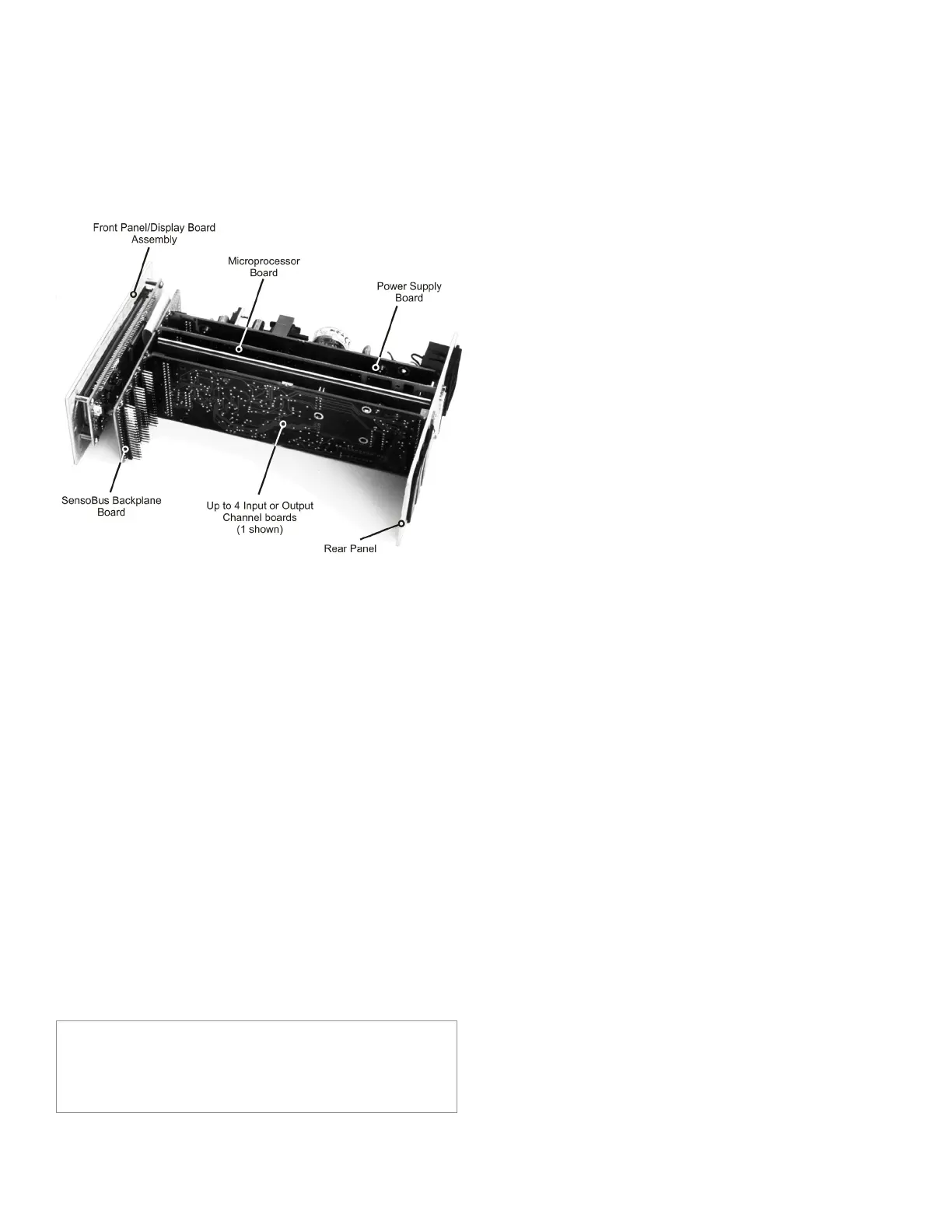
The figure below shows the names and locations of the printed
circuit boards.
Figure 4-3: Internal Arrangement of SC2000
Below is a description of each printed circuit board.
• TheSensoBus Backplane Board serves as the connection
between all boards in the instrument.
• TheFrontPanel/Display Board Assembly contains the dis-
play and all front panel controls.
• ThePower Supply Board contains the +15V, -15V and +5V
power supplies.
• TheMicroprocessor Board contains the microprocessor,
ROM software storage chip, and the System connector.
• TheHardware Input/Output Channel Boards plug into the
remaining four slots of the SensoBus Backplane Board.
4.3.8 Cleaning
Turn off the instrument and unplug all connectors. Use a soft
cloth or tissue and a mild cleaner. Do not use liquid or aerosol
cleaners. Do not allow any cleaner inside the instrument.
4.3.9 Vehicle Power Option
Model SC2000 instruments are available with a vehicle power op-
tion for operation with batteries and linear dc power supplies. See
“Specifications” on page 9 voltage and power requirements.
NOTICE
Due to the momentary startup inrush current of the instru-
ment’s power supply, the use of switching power supplies with
the SC are not recommended.
4.3.10 Fuse Replacement
The power-line fuses of AC-powered instruments are located
within the instrument’s power entry module on the rear panel. Use
two 2A, 250V fast-blow fuses (p/n 029-3026-00).

 Loading...


