Honeywell Sensing and Control 15
SC 2000, SC2001, SC3004
Rev. G, 008-0608-00
4.5 Model SC3004
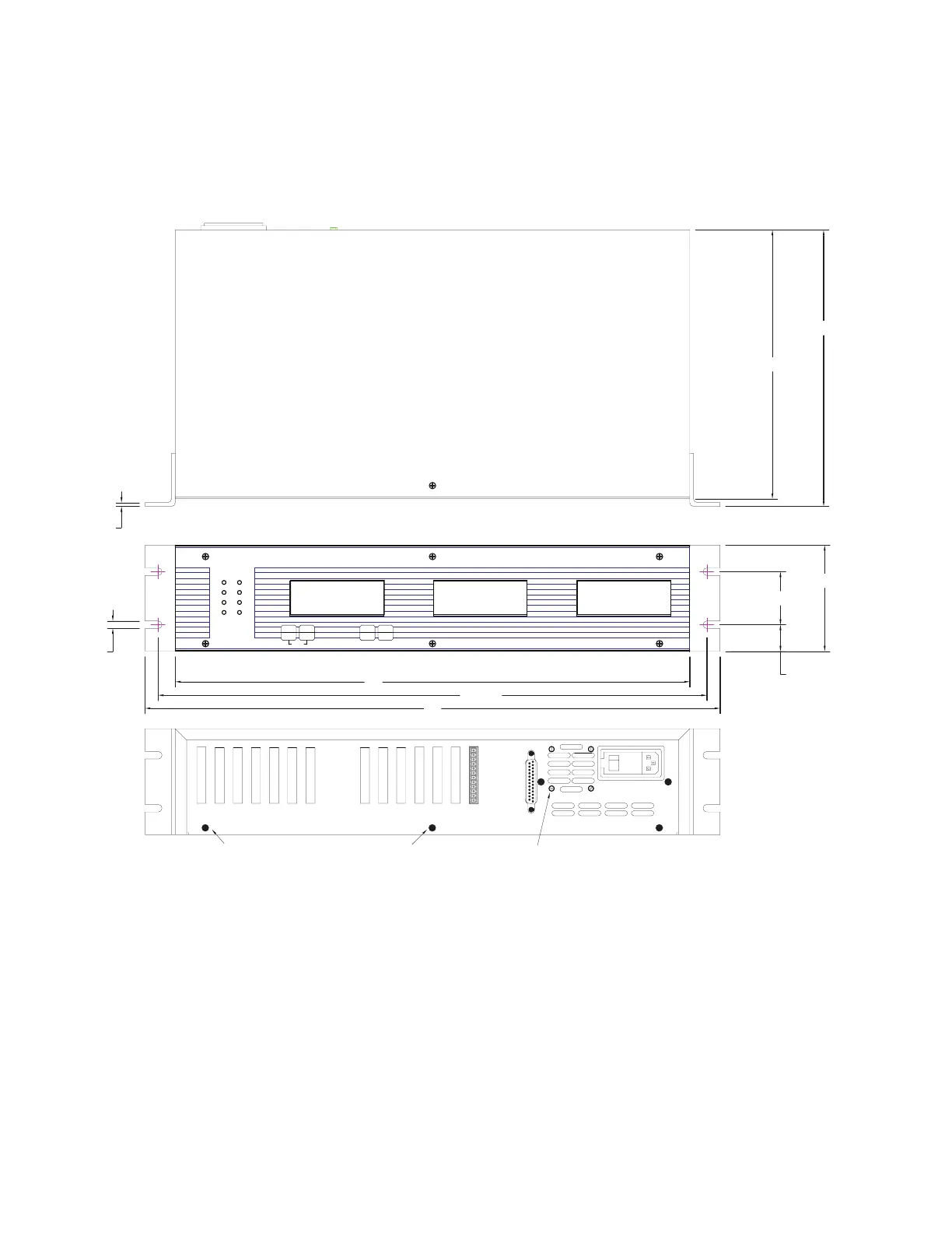
4.5.1 External Arrangement
Figure 4-5: External Arrangement of Model SC3004
L-4L-8
ENTER
L-3
L-2
L-7
L-6
L-1L-5
EXIT
CHAN.TAREVALUE
RUN
SETUP
UP
CLEAR
DOWN
MENU
0123456789ABCDEFGHIJ
0123456789ABCDEFGHIJ
0123456789ABCDEFGHIJ
0123456789ABCDEFGHIJ
0123456789ABCDEFGHIJ
0123456789ABCDEFGHIJ
0123456789ABCDEFGHIJ
0123456789ABCDEFGHIJ
0123456789ABCDEFGHIJ
0123456789ABCDEFGHIJ
0123456789ABCDEFGHIJ
0123456789ABCDEFGHIJ
.250"
2X, .125"
CABLE SHIELD CONNECTION SCREWS
(QTY. 4)
FAN MOUNTING SCREWS
DO NOT REMOVE
MADE IN USA
17"
18.125"
19"
4X, .875"
2X, 1. 75"
3.5"
9.125"
8.875"
4.5.2 Rear Panel
The pinout for the 25-pin System connector is provided later in
this chapter. The pinouts for the individual channels are located
in the chapter for that channel.
4.5.3. Panel Mounting
The panel space necessary conforms to the EIA 19” rack-mount
standard. Panel mounting ears are attached to the instrument.
4.5.4 Bench Mounting
Panel mounting ears are attached to the instrument, and may be
removed if they are not needed.
 Loading...


