Connected dots
Connected dots draws a straight line among the data points on the display.
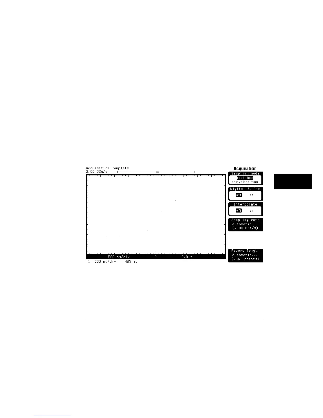
On waveforms where there are only a few dots representing the acquired
data points, you may find it easier to have a sense of what the waveform looks
like. Figure 9-2 shows a waveform with just dots, and figure 9-3 shows a
waveform that is using connected dots.
Connected dots works on channels, functions, and waveform memories.
However, connected dots is not available when the mask test is running.
In the real-time sampling mode, a better solution is to turn on the
interpolator. The interpolator reconstructs the waveform much better than
connected dots, and the interpolator also improves the measurement
repeatability of the oscilloscope. Figure 9-4 shows the same waveform as
figure 9-3 except that the interpolator is turned on.
Interpolate is only available in the real-time sampling mode so you use
connected dots in the equivalent-time sampling mode. But, remember that
connected dots slows down the display update rate of the oscilloscope
slightly because it takes time for the oscilloscope to draw the lines among the
data points.
Dots only
Figure 9-2
Display Menu
Draw Waveform
9–7