Glitch timing requirements
For the oscilloscope to trigger on a glitch, the opposite polarity of the glitch
must be present for at least 5 ns. The polarity of the glitch is determined by
the trigger level. Voltages above the trigger level are of positive polarity, and
voltages below the trigger level are of negative polarity. For example,
Figure 18-2 shows a positive polarity glitch. The signal must be below the
trigger level for at least 5 ns for the oscilloscope to detect the glitch. If a
negative polarity glitch was selected, then the signal must be above the
trigger level for at least 5 ns.
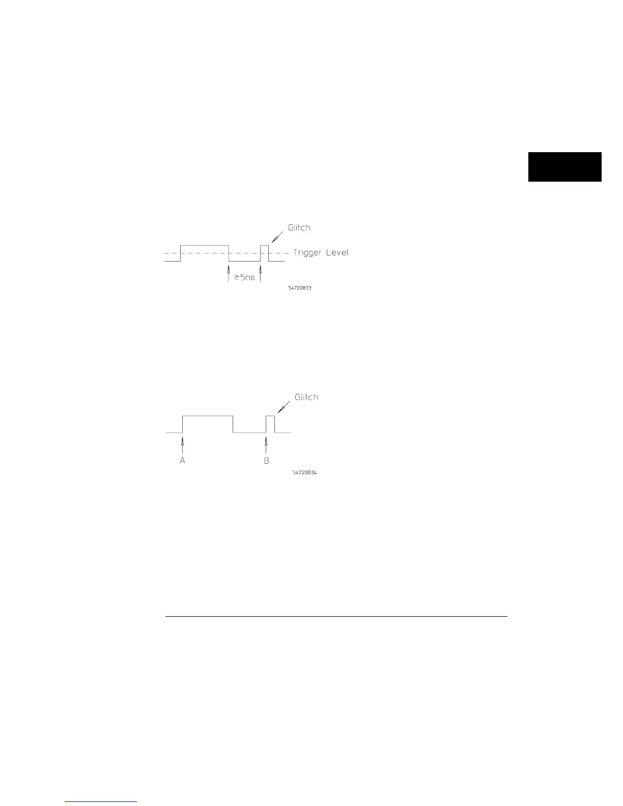
The opposite polarity of the glitch must be present for at least 5 ns
If the selected glitch width is from 3 ns to 19 ns, the time between similar
edges must be greater than the selected glitch width. Figure 18-3 illustrates
the timing between like edges. For example, if the selected width is 8 ns,
then the time from point A to point B must be greater than 8 ns.
For glitch widths of 3 ns to 19, the time from A to B must be greater than the selected width
Figure 18-2
Figure 18-3
Trigger Menu
Mode
18–9