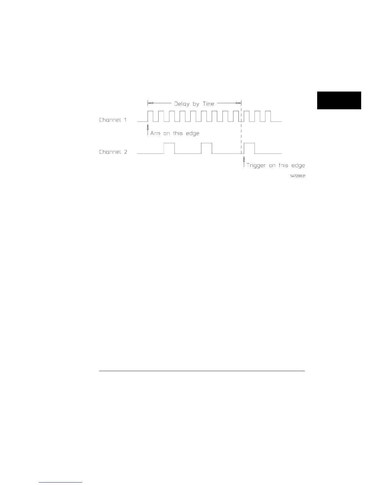
Figure 18-6 shows a delay-by-time timing diagram. You may notice that the
arming event is channel 1, and the trigger event is channel 2. By changing
the amount of delay, you can look at various events in a pulse train without
the effects of jitter. The first event to satisfy the trigger conditions after the
delay timer times out triggers the oscilloscope.
Example of a when a trigger occurs on a delay by time timing diagram
Figure 18-6
Trigger Menu
Mode
18–15