Probe Loading
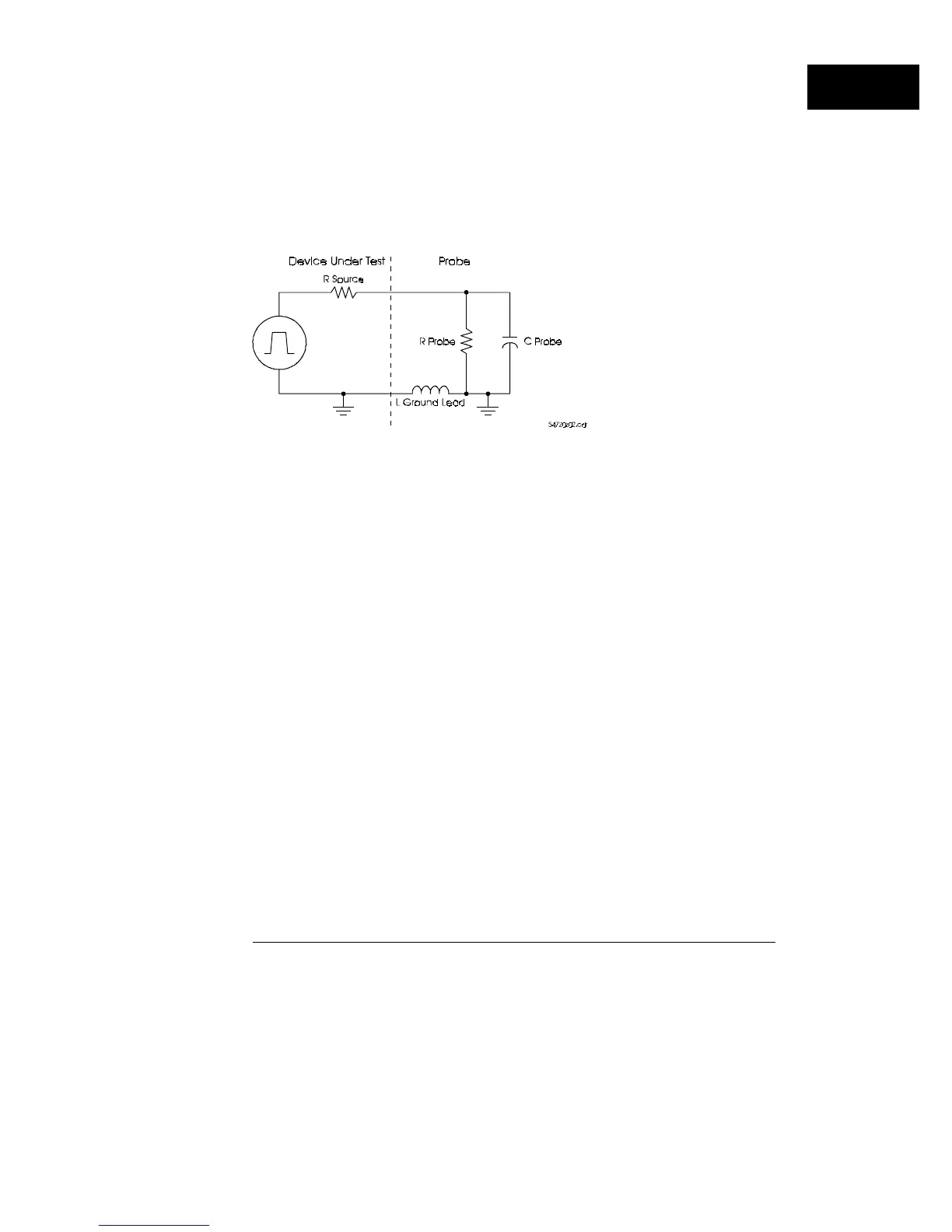
Figure 1-8 shows a simplified diagram of the circuit with the probe attached
to indicate the principal loading effects. The probe load has both resistive
and capacitive components. In addition to this, the inductance in the probe
ground lead can cause ringing.
Simplified equivalent circuit of DUT and probe
Figure 1-8
How the Oscilloscope Works
Choosing Probes
1–21