4-4 ES User’s Guide
Using Instrument Functions
Using Markers
NOTE The frequency position of the markers is coupled between the two
measurement channels. Changing the frequency of a marker on one
measurement channel will also change the frequency of the marker on
the other measurement channel.
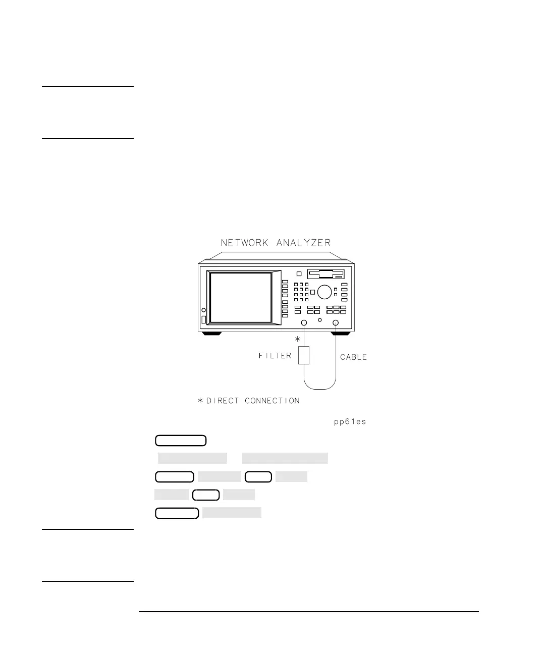
The examples in this section are shown with an S
21
forward
transmission measurement of a filter. To follow along with these
examples, use the filter that was shipped with your analyzer, connect the
equipment as shown, and set up the analyzer by pressing the keys shown
below Figure 4-2.
Figure 4-2 Connect the Filter to the Analyzer
( or )
NOTE When you make a hardcopy of your measurement results that contain
displayed markers, you can choose to have a marker table appear on the
hardcopy. Refer to “Printing and Plotting Measurement Results” on
page 4-78.
PRESET
FREQ
349
SCALE
 Loading...


