319
MLD configuration examples
Basic MLD functions configuration example
Network requirements
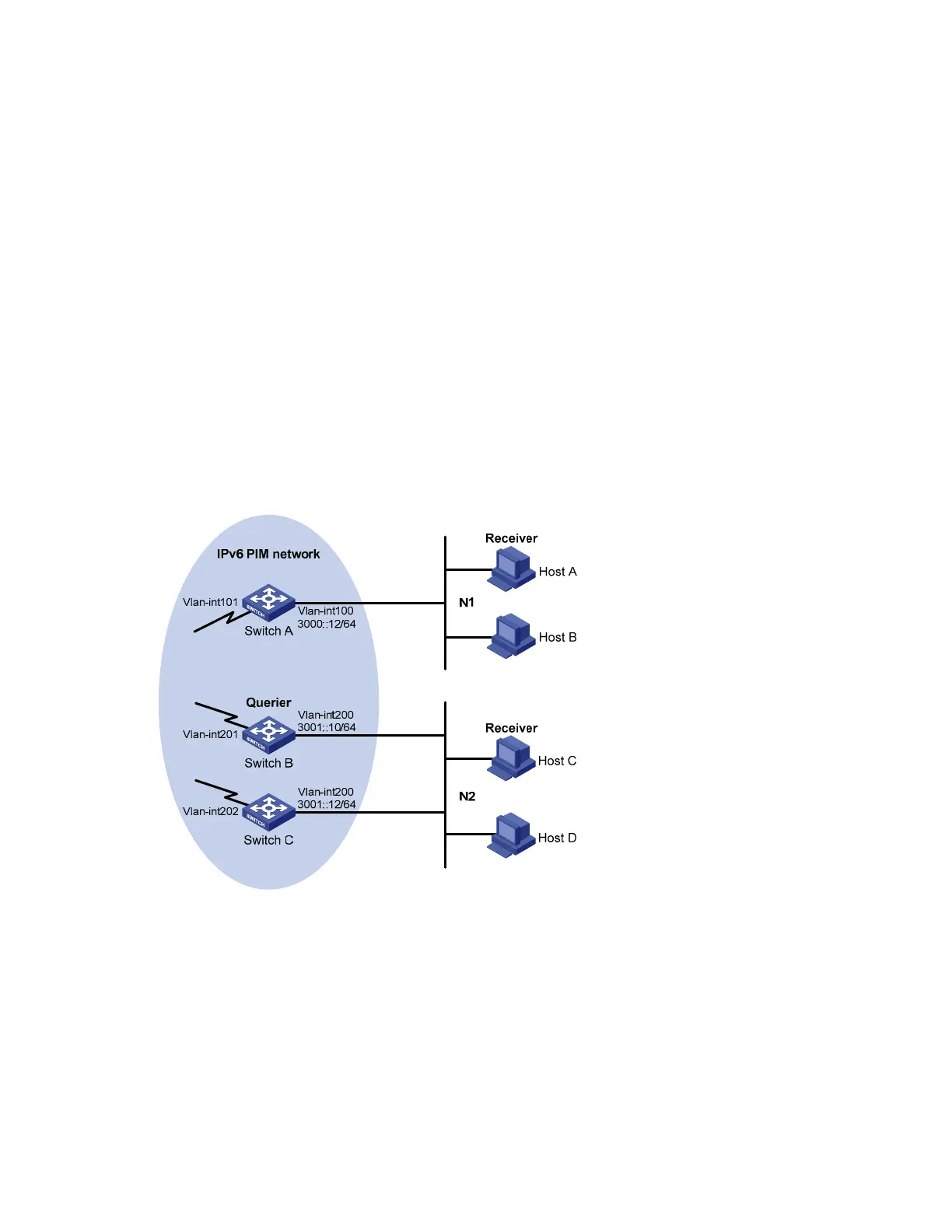
• As shown in Figure 83, receivers receive VOD information in the multicast mode. Receivers of
different organizations form stub networks N1 and N2, and Host A and Host C are multicast
receivers in N1 and N2 respectively.
• Switch A in the IPv6 PIM network connects to N1, and Switch B and Switch C connect to N2.
• Switch A connects to N1 through VLAN-interface 100, and to other devices in the IPv6 PIM network
through VLAN-interface 101.
• Switch B and Switch C connects to N2 through their own VLAN-interface 200, and to other devices
in the IPv6 PIM network through VLAN-interface 201 and VLAN-interface 202 respectively.
• MLDv1 is required between Switch A and N1. MLDv1 is also required between the other two
switches—Switch B and Switch C—and N2. Switch B acts as the MLD querier because it has a
lower IPv6 address.
Figure 83 Network diagram for basic MLD functions configuration
Ethernet Ethernet
Configuration procedure
1. Enable IPv6 forwarding and configure IPv6 addresses and IPv6 unicast routing
Enable IPv6 forwarding on each switch and configure an IP address and prefix length for each interface
as shown in Figure 83. Th
e detailed configuration steps are not discussed in this document.
Configure OSPFv3 for interoperation between the switches. Ensure the network-layer interoperation
among the switches on the IPv6 PIM network and dynamic update of routing information between the
switches through a unicast routing protocol. The detailed configuration steps are omitted here.
2. Enable the IPv6 multicast routing, and enable IPv6 PIM-DM and MLD.

 Loading...


