39
Static port configuration example
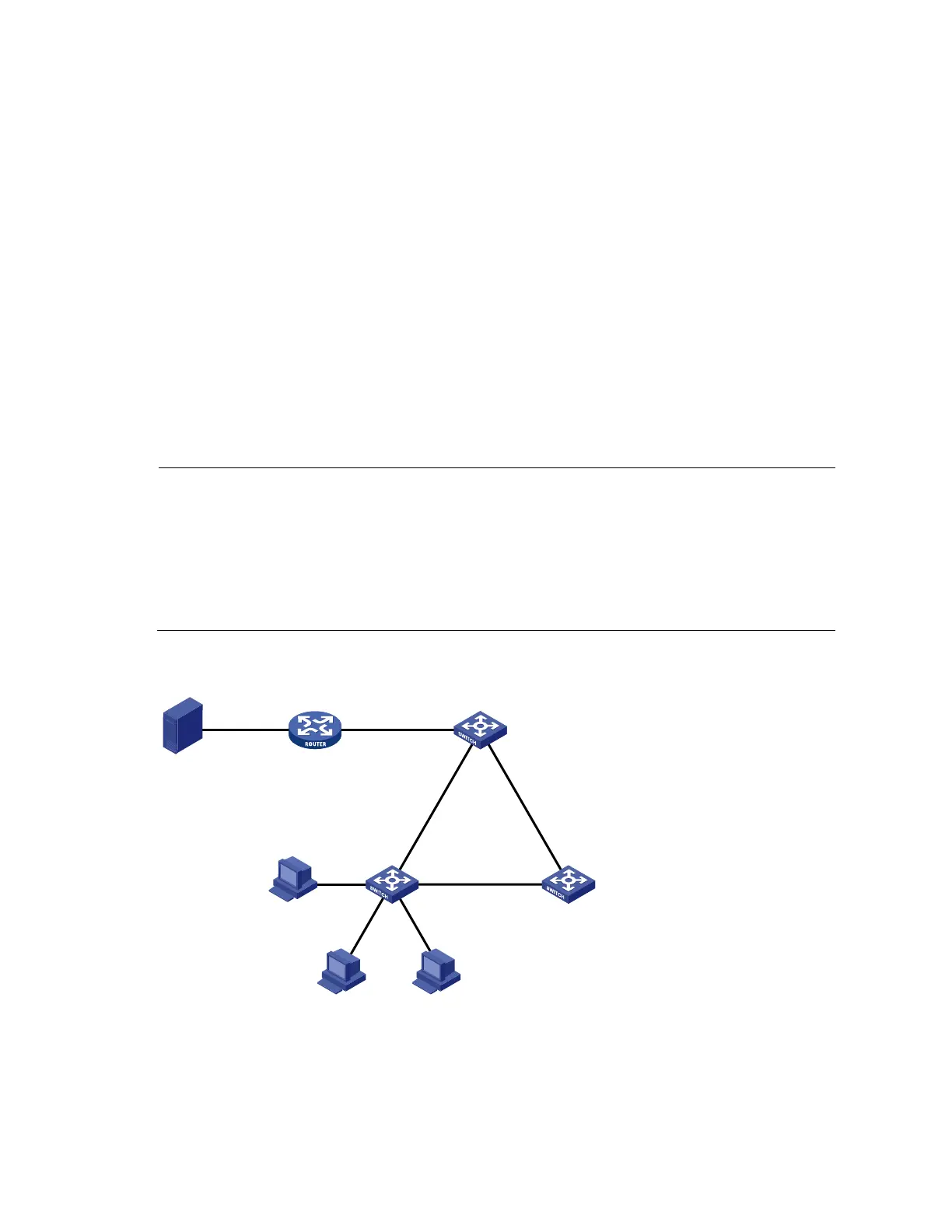
Network requirements
• As shown in Figure 15, Router A connects to a multicast source—Source—through GigabitEthernet
1/0/2, and to Switch A through GigabitEthernet 1/0/1.
• IGMPv2 will run on Router A, and IGMPv2 snooping will run on Switch A, Switch B and Switch C,
with Router A acting as the IGMP querier.
• Host A and host C are permanent receivers of multicast group 224.1.1.1. GigabitEthernet 1/0/3
and GigabitEthernet 1/0/5 on Switch C are required to be configured as static member ports for
multicast group 224.1.1.1 to enhance the reliability of multicast traffic transmission.
• Suppose STP runs on the network. To avoid data loops, the forwarding path from Switch A to
Switch C is blocked under normal conditions, and multicast traffic flows to the receivers attached to
Switch C only along the path of Switch A—Switch B—Switch C.
• Configure GigabitEthernet 1/0/3 that connects Switch A to Switch C as a static router port, so that
multicast traffic can flow to the receivers nearly uninterruptedly along the path of Switch A—Switch
C in the case that the path of Switch A—Switch B—Switch C gets blocked.
NOTE:
If no static router port is configured, when the path of Switch A—Switch B—Switch C
ets blocked, at
least one IGMP query-response cycle must be completed before the multicast data can flow to the
receivers along the new path of Switch A—Switch C. Namely multicast delivery will be interrupted
during this process.
For more information about the Spanning Tree Protocol (STP), see the
Layer 2—LAN Switching
Configuration Guide
.
Figure 15 Network diagram for static port configuration
Source
1.1.1.1/24
Router A
IGMP querier
GE1/0/1
10.1.1.1/24
GE1/0/2
1.1.1.2/24
Switch A
Switch C
Switch B
GE1/0/1
G
E
1
/
0
/
2
G
E
1
/
0
/
3
G
E
1
/
0
/
1
GE1/0/2
GE
1
/
0
/
1
GE1/0/2
Host C
Host B Host A
Receiver
Receiver
G
E
1
/
0
/
3
GE
1
/
0
/
4
GE1/0/5

 Loading...


