211
# View the brief MSDP peer information on Switch E.
[SwitchE] display msdp brief
MSDP Peer Brief Information of VPN-Instance: public net
Configured Up Listen Connect Shutdown Down
1 1 0 0 0 0
Peer's Address State Up/Down time AS SA Count Reset Count
192.168.3.1 Up 00:16:40 ? 13 0
Anycast RP configuration
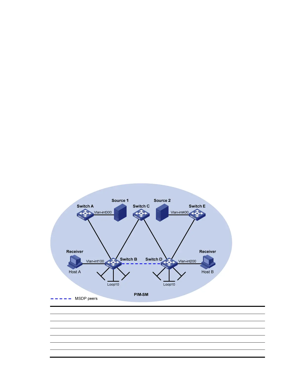
Network requirements
• As shown in Figure 60, the PIM-SM domain has multiple multicast sources and receivers. OSPF runs
within the domain to provide unicast routes.
• Configure the Anycast RP application so that the receiver-side DRs and the source-side DRs can
initiate a join message to their respective RPs that are the topologically nearest to them.
• On Switch B and Switch D, configure the interface Loopback 10 as a C-BSR, and Loopback 20 as
a C-RP.
• The router ID of Switch B is 1.1.1.1, and the router ID of Switch D is 2.2.2.2. Set up an MSDP
peering relationship between Switch B and Switch D.
Figure 60 Network diagram for Anycast RP configuration
Loop0
Loop2
0
Lo
op20
L
oop0
V
l
a
n
-
i
n
t
1
0
1
V
l
a
n
-
i
n
t
1
0
1
V
l
a
n
-
i
n
t
1
0
2
V
l
a
n
-i
n
t
1
0
2
V
l
a
n
-
i
n
t
1
0
3
V
l
a
n
-
i
n
t
1
0
3
V
l
a
n
-
i
n
t
1
0
4
V
l
a
n
-
i
n
t
1
0
4
Device Interface IP address Device Interface IP address
Source 1 — 10.110.5.100/24 Switch C Vlan-int101 192.168.1.2/24
Source 2 — 10.110.6.100/24 Vlan-int102 192.168.2.2/24
Switch A Vlan-int300 10.110.5.1/24 Switch D Vlan-int200 10.110.3.1/24
Vlan-int103 10.110.2.2/24 Vlan-int104 10.110.4.1/24
Switch B Vlan-int100 10.110.1.1/24 Vlan-int102 192.168.2.1/24
Vlan-int103 10.110.2.1/24 Loop0 2.2.2.2/32

 Loading...


