Identifying components and LEDs 15
Item Description Status
1
Serial connector Serial RS232 DB-9 connector with PC standard
pinout
2
UID LED Blue = UID on
Dark = UID off
3
Active Onboard
Administrator LED
An LED that indicates which Onboard
Administrator is active
4
Health LED Green = OK
Red = Critical error
5
USB A USB 2.0 Type A connector that connects
supported USB devices
6
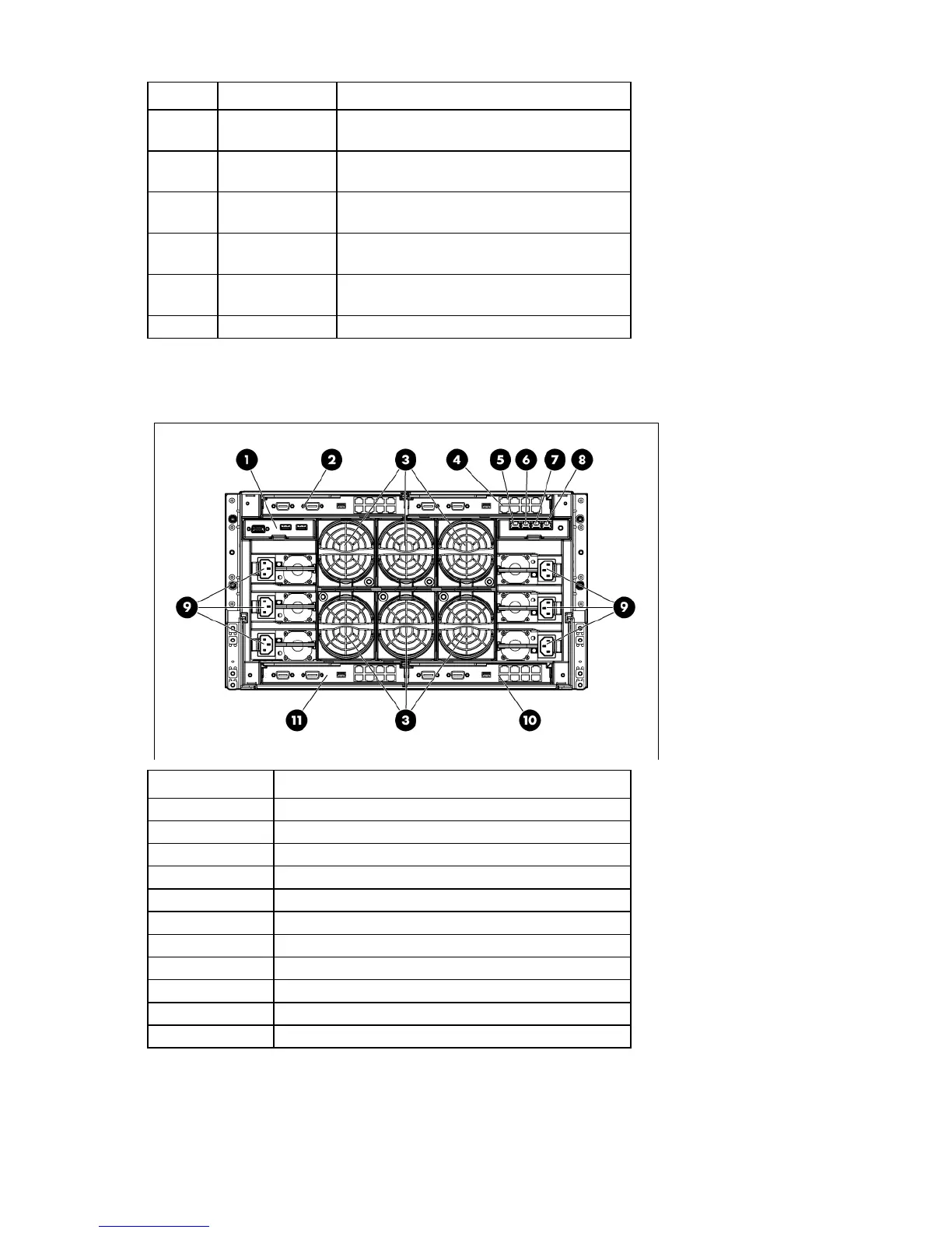
Enclosure rear components
Item Description
1
KVM module bay
2
Interconnect bay 1
3
Fan bays ("Fan bay numbering" on page 16)
4
Interconnect bay 2
5
Enclosure link-down port
6
Enclosure link-up port
7
Onboard Administrator 1/iLO port
8
Onboard Administrator 2/iLO port
9
Power supply bays
10
Interconnect bay 4
11
Interconnect bay 3