PWRCMD—Power command, P2
4 PWROK Gray
5 GND Black
6 PSU_DETECT (empty)
CPU power cable, P3 Pin Color Signal
1 BLK GND
2 BLK GND
3 BRN 12V CPU
4 BRN 12V CPU
CAUTION: Never connect the PCIe power cable to the system board when
power is on. If you do so, the system board can be damaged and the warranty
voided. Ensure that you can tell which power cable connects to the PCIe x16
graphics card and which power cable connects to the system board. These two
cables have different pin counts and different colors. The PCIe power cable has
a 6-pin black connector, and the CPU power cable has an 4-pin white connector.
To see a picture of the PCIe cable and where it must be connected, see
Removing
and installing expansion cardson page 112.
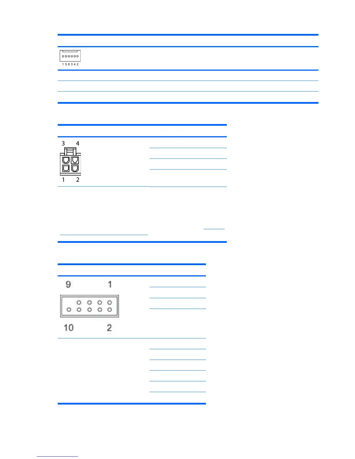
Internal USB 1 2x5 Pin Signal
1 +5V
2 +5V
3 USB6#
4 USB9#
CAUTION: Possible equipment damage.
The 2x5 connector can be mated to either
a wide 2x5 option cable connector or a
narrow 1x5 option cable connector.
To prevent damage to the connectors,
always connect a narrow 1x5 option cable
connector to pins 1,3,5, and 7 only of the
2x5 connector (pin 9 is not keyed on the
connector).
5 USB6
6 USB9
7 GND
8 GND
9 (not keyed)
10 DETECT
174 Appendix A Connector pins ENWW
 Loading...