Chapter 6 Function Introduction Shenzhen Hpmont Technology Co., Ltd
―110― HD30 Series Inverters User Manual
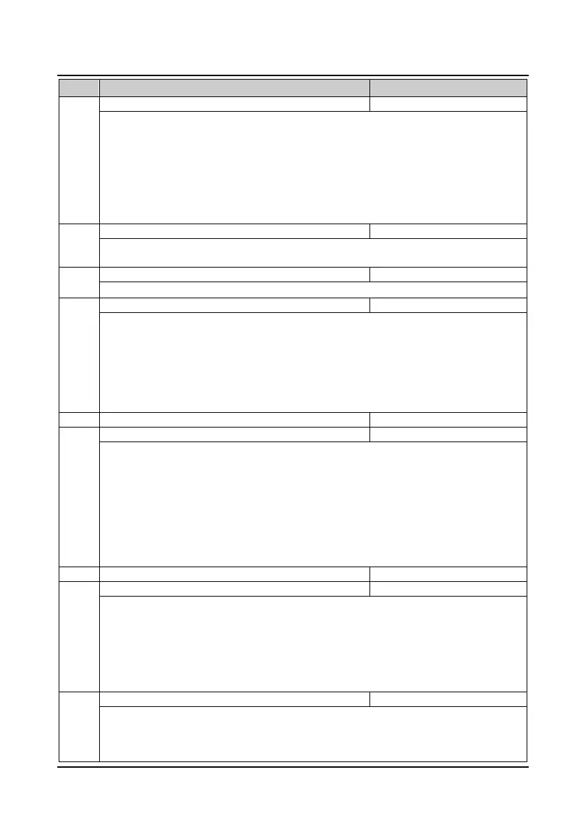
No. Name Description Range
factory setting
F19.01 Master/Auxiliary setting calculation 0
5
0
It defines the calculating relationship between the final setting frequency and the master/auxiliary
freqeuency.
0: Master setting + auxiliary setting.
1: Master setting − auxiliary setting.
2: MAX (master setting, auxiliary setting).
3: MIN (master setting, auxiliary setting).
4:
Master setting + auxiliary setting × master setting maximum value of master setting
⁄
.
5:
Master setting – auxiliary setting × master setting maximum value of master setting
⁄
.
F19.02 Analogue auxiliary setting coefficient 0.00
9.99
1.00
First, calculate the gain by using F19.02, then calculate auxiliary frequency according to the frequency
characteristic curve of Group F05. When F19.00 = 4,5, F19.02 is enabled.
F19.03 Initial value of digital auxiliary frequency 0.00
F00.06
0.00
Only when F19.00 = 1 or 2 will F19.03 be enabled and provide the initial value for the two methods.
F19.04 Control selection of digital auxiliary frequency 00
11
00
Only when F19.00 = 1 or 2 will F19.04 be enabled.
Units: Save selection at power outage
• 0: Not save auxiliary frequency at power outage.
• 1: The auxiliary frequency will be saved to F19.03 at power outage.
Tens: Frequency disposal when the inverter stops
• 0: Maintain the auxiliary frequency when the inverter stops.
• 1: The auxiliary frequency clears to zero when the inverter stops.
F19.05 Adjustment selection of setting frequency 0
2
1
Adjustment coefficient of setting frequency
F19.05 and F19.06 is to set the adjustment mode of setting frequency (the compounded frequency is
computed by master setting frequency plus auxiliary setting frequency).
0: No adjustment.
• Setting frequency = master setting frequency + auxiliary setting frequency.
1: To adjust as per the max. output frequency of F00.06.
• Setting frequency = (master setting frequency + auxiliary setting frequency) + F00.06 × (F19.06 -
100%).
2: To adjust as per the current frequency.
• Setting frequency = (master setting frequency + auxiliary setting frequency) × F19.06.
Control selection of cooling fan
F19.08 Cooling fan controls delaying time 0.0
600.0
30.0s
0: Auto stop mode.
• The fan runs all the time when the inverter is in running status. After the inverter stops for the time
set by F19.08, the fan stops if the inverter is not overheated. The fan will continue running if the
overheat protection is activated.
1: Immediate stop mode. The fan runs all the time when the inverter is in running status and stops when
the inverter stops.
2: The fan runs continuously when power on. The fan runs continuously after the inverter is switched on.
F19.09 Droop control 0.00
10.00
0.00Hz
This function is used in the application that several inverters drive one motor. The function can make the
inverters share the load equally.
When the load of one inverter is heavier, this inverter will reduce its output frequency to shed part of the
load according to the setting of F19.09.

 Loading...


