Chapter 3 Electrical Installation
MONT20 User Manual V1.6 11
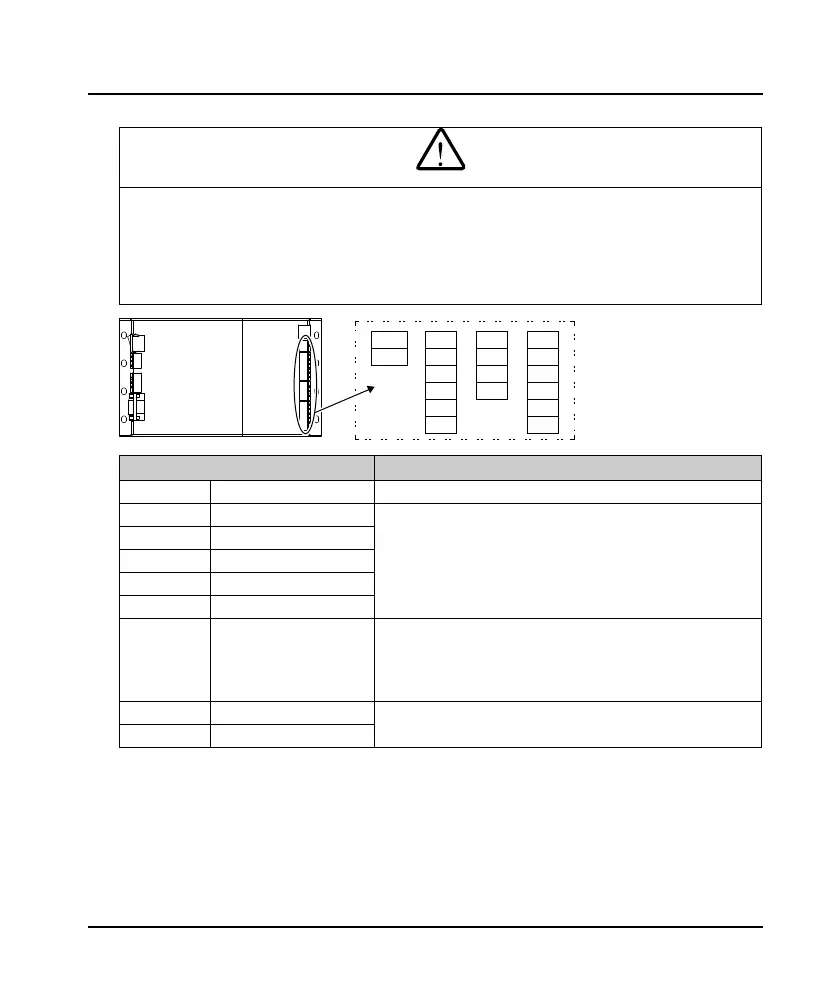
3.3.3 Control Terminal
• If the control circuit is connected to the external device with an accessible port during power on, pay attention to
add an additional insulation protection isolation device to ensure that the original voltage level of the external
device is not changed.
• If connect the communication terminal of the control circuit to the PC, choose RS485/232 isolating converter
which meets the safety requirement.
• It is strictly forbidden to connect control terminals other than relay terminals to AC 220V voltage.
Terminal Description
CAN+, CAN- CAN input CAN communication terminal port
DI1 - DI5 Digital input
Optical-cupler isolated input signal
Connect to COM (ON): Command is valid
Disconnect to COM (OFF): Command is invalid
• Use F06.03 - F06.07 to set DI1 - DI5 function
+24V power supply, Max. output current is 200mA
OD Open door command input
CD Close door command input
P24 +24V power supply
COM Input reference ground
PA, PB, PC Replay output
Contact rating: 125VAC/0.5A or 24VDC/1A
• F06.01 set the function
• F06.00 set low level or high level is valid
PA, PB: Normally closed; PA, PC: Normally open
DOA, CME Complete OD relay
DOA, DCA: Normally closed; CME is isolated from COM
• F06.00 sets low level or high level is valid
DCA, CME Complete DC relay
Control
terminal
COM
DI5
CD
OD
CAN+
CAN-
DI1
DI2
DI3
DI4
P24
COM
PA
PB
PC
DOA
DCA
CME
MONT20
 Loading...
