Chapter 3 Electrical Installation
12 MONT20 User Manual V1.6
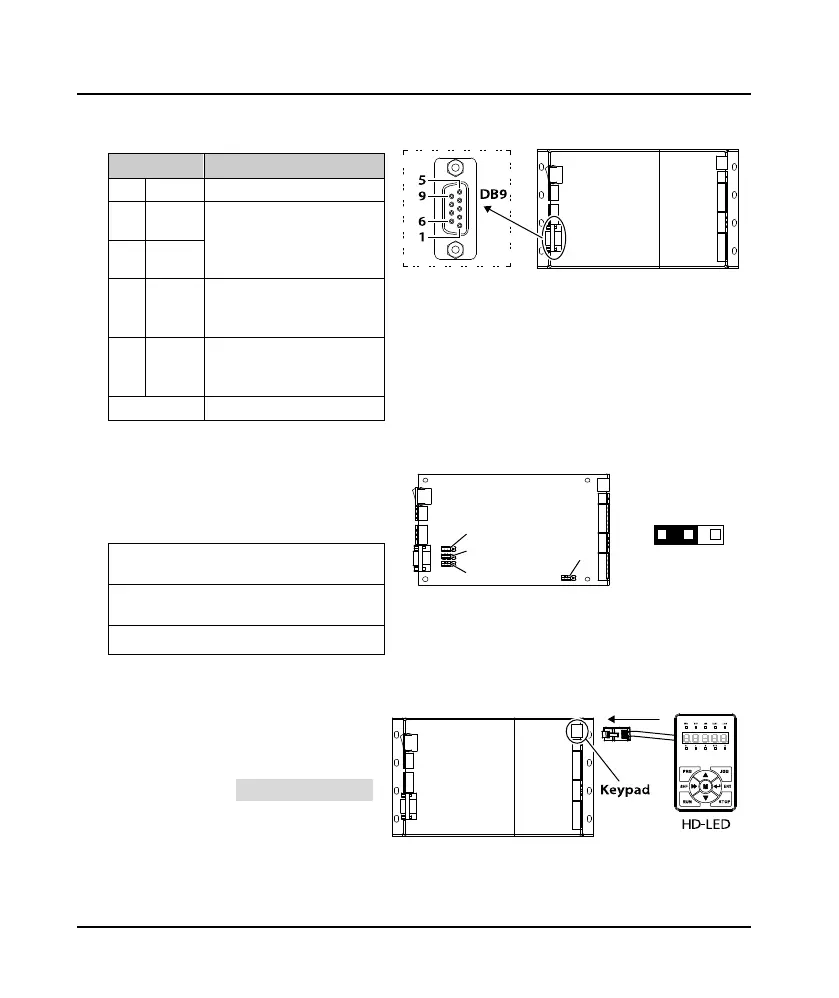
3.3.4 Connecting Encoder
DB9 of MONT20 is for connecting encoder.
Pin Description
1 COM Encoder power ground
2 A
A/B phase signal of encoder,
there is 90° difference which is
used to judge the rotary speed
and direction
6 B
3, 7 Z
Z phase signal of encoder, the
falling edge is valid, used for
positioning the datum point
5
Encoder
power
supply
+24V, Max. output current is
100mA, optional 12V
4, 8, 9 Reserved
3.3.5 Set the Encoder Power Supply to 12V
The encoder power supply defaults to 24V
and optionally 12V, and the operation is
shown in the following table.
1.
Remove the cover and loosen the 4 screws
on the left and right sides.
2.
Set jumpers. Short-circuited to pin 1, 2 of
jumper J1 - J4.
3. Install the cover.
J1
-
J4
3.3.6 External Keypad
MONT20 can set and view the parameters
through the external keypad of the keypad
terminal. The connection is shown in the
right figure. Refer to Chapter 4, on page 13
for more details.
The external keypad is HD-LED. If needed,
please order goods.
 Loading...
