Chapter 6 Application Debugging
48 MONT20 User Manual V1.6
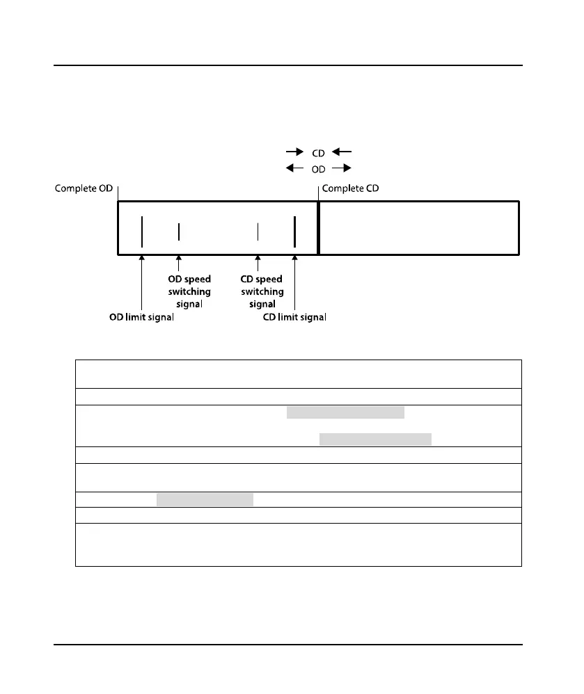
6.3 Speed Control
With four external limit switches, MONT20 can realize speed control, no longer need external encoder
to detect the door position. The installation position of each limit switch (signal connection) are shown
in Figure 6-3.
Figure 6-3 Speed control switches and their installation
Main Steps:
1.
Connect OD limit, OD speed switch, CD limit and CD speed switch to DI1 - DI4 respectively, and connect
common terminal to COM.
2. Then turn on the power supply switch of MONT20.
3.
Manually open and close the door, observe the d01.09 (input terminal status 1) by the keypad, confirm the
limit switches and signals are normal.
If the external switch is normally open (NO), it needs set DI1 - DI4 function (group F06) to be NO.
4. Refer to section 6.3.2 and section 6.3.3 for the debugging of OD/CD curve.
5.
Confirm the fully signal of door motor according to elevator main control panel (F06.00 = 1, relay NO; F06.00
= 1, relay NC, default).
6. Set F00.03 = 1 (terminal control mode), and integrate into elevator system.
Note:
1. Observe d01.09, which shows the signal change is abnormal.
Countermeasure: Check the switch installation and the connection of switches and MONT20. Make sure
they are correct and then proceed to step 3 and 4.
 Loading...
