Chapter 6 Application Debugging
50 MONT20 User Manual V1.6
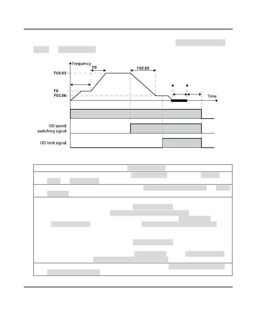
6.3.2 Speed Control OD Running
Set parameters of group F03 and F05 that relates to speed control. Define speed switching contact
(F03.04) and limit signal (F03.07) accurately. They are a premise for MONT20 to output perfect OD
curve. The OD running speed curve is shown in
Figure 6-4.
Figure 6-4 Speed control OD process
Process Description:
1. When OD command is valid, door motor Acc. to starting speed (F03.01) and runs at constant speed.
2.
Time counts from OD starting. When time reaches starting time (F03.00), door motor Acc. to OD speed
(F03.03) with Acc. time (F03.02) and runs at F03.03.
3.
When OD speed switch signal is valid, door motor Dec. to creeping speed at OD ending (F03.06) with OD Dec.
time (F03.05) and runs at F03.06.
4. F00.06 = 0 (open-loop vector control of Asyn. motor):
• When OD limit signal is valid, door motor runs at creeping speed (F03.06);
• Start timing when output torque ≥ switching torque (F05.00) × motor rated torque, or OD limit signal is
valid, when the time exceeds F06.21, enter the OD torque holding state; The OD torque (F05.01) waits until
switching time (F05.03) is finished, and then switch to final holding torque of complete OD (F05.02), the OD
process is finished.
F00.06 = 3 (flux vector control of Syn. motor):
• When OD limit signal is valid, door motor runs at crepping speed (F03.06);
• Time counts from OD limit signal is valid. When the time exceeds F06.21, door motor enters OD torque
holding status, and F06.20 sets output frequency; OD torque (F05.01) waits until switching time (F05.03) is
finished, and switches to final holding torque of complete OD (F05.02), the OD process is finished.
5.
When OD command is invalid, OD torque judges the action according to F06.11 (door motor action when
running command is cancelled).
3.01
3.02
OFFOD ON
OFF ON
OFF
ON
F05.01
F05.00
F05.02
F05.03F03.00
 Loading...
