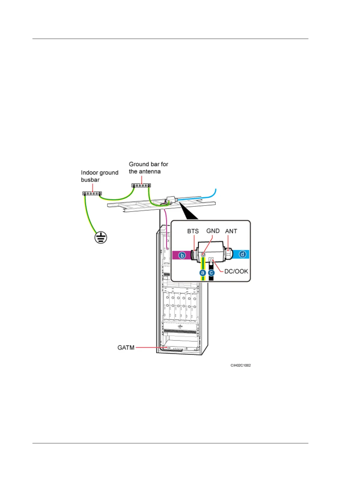
Procedure
Step 1 Connect the GND port on the straight DIN Bias-Tee to the ground bar of the antenna through
the PGND cable, and then fix the straight DIN Bias-Tee on the cable tray.
Step 2 Connect the ANT port on the straight DIN Bias-Tee to the 7/8" feeder.
Step 3 Connect the DC/OOK port on the Bias-Tee to the ports from ANT0 to ANT5 on the GATM
through the RET control signal cable.
Step 4 Connect the BTS port on the Bias-Tee to the RF output port on the RFU through the 1/2" jumper,
as shown in Figure 10-8.
Figure 10-8 Installing the straight DIN Bias-Tee
(1) Indoor ground bar
(2) Ground bar for the antenna (3) 7/8" feeder
(4) 1/2" jumper (5) RET control signal cable (6) GATM
Step 5 Attach color rings to the RF jumper by referring to Attaching the Color Ring.
----End
BTS3900L (Ver.C)
Installation Guide
10 (Optional) Installing the Modules
Issue 07 (2013-11-08) Huawei Proprietary and Confidential
Copyright © Huawei Technologies Co., Ltd.
51