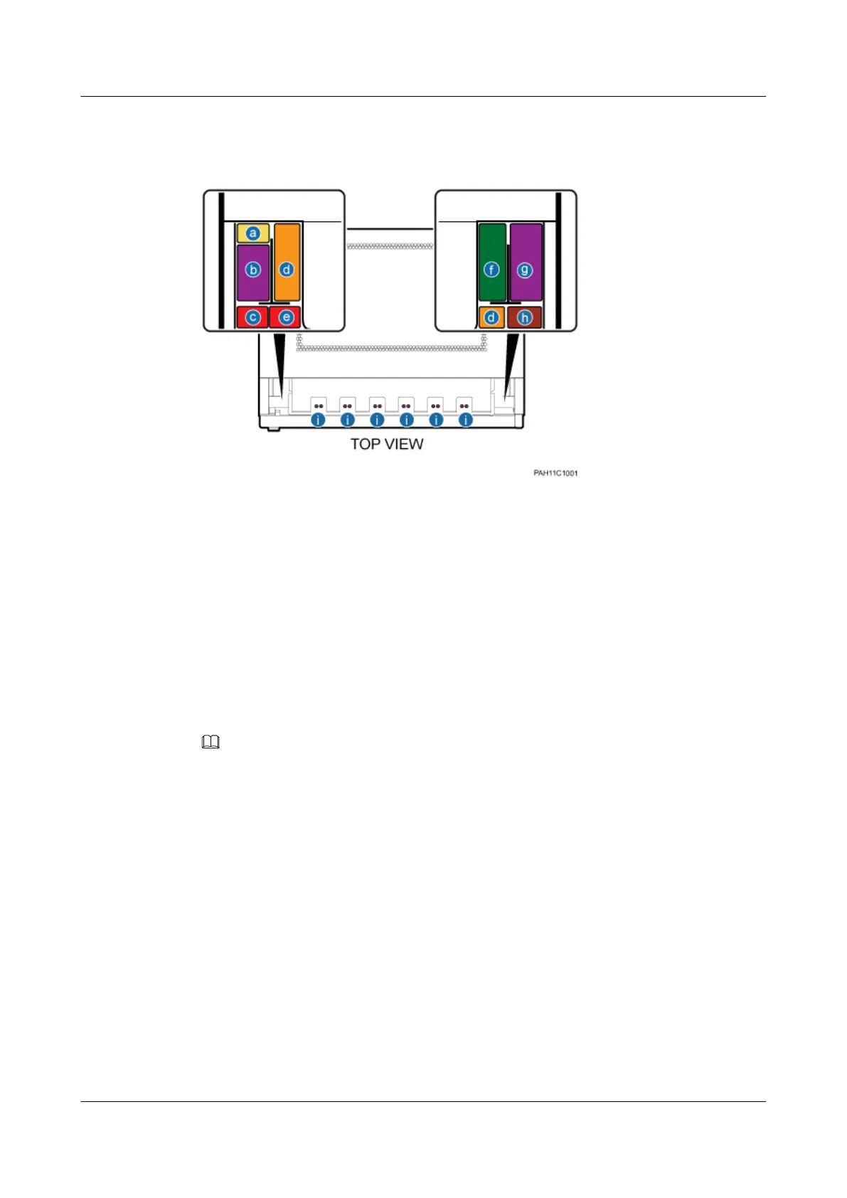
Figure 11-8 shows the cable routes in the cabinet.
Figure 11-8 Cable routes
(a) PGND cable and the lower
DCDU input power cable
(b) Jumpers on the left side (c) The upper DCDU input power
cable in the capacity expansion
scenario
(d) CPRI fiber optic cable (e) Not defined (f) Transmission cables and signal
cables
(g) Jumpers on the right side (h) Not defined (i) Jumpers in the lower
compartment
Binding Cables
Bind the cables according to the routes in Figure 11-8 and methods in Figure 11-9 and Figure
11-10.
NOTE
Locate the cables around the binding bracket according to the figures showing the spatial positions of the
cables. Bind the cables to the nearest points on the binding bracket.
BTS3900L (Ver.C)
Installation Guide 11 Installing the Cables
Issue 07 (2013-11-08) Huawei Proprietary and Confidential
Copyright © Huawei Technologies Co., Ltd.
70