FusionModule800 Smart Small Data Center
Installation Guide (Six Fans)
Copyright © Huawei Technologies Co., Ltd.
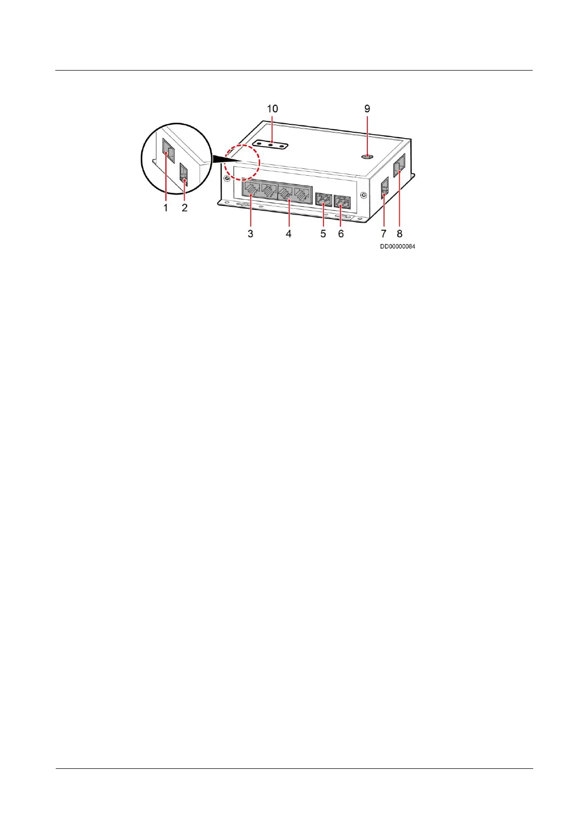
Figure 4-39 Ports on a smart ETH gateway
(1) PWR_IN cascading
power port
(2) FE_1 cascading signal
port
(5) 48V_OUT1 power output
port
(6) 48V_OUT2 power
output port
(7) FE_2 cascading signal
port
(8) PWR_OUT cascading
power port
Procedure
Step 1 Take out the ground cable from the smart ETH gateway fitting bag and connect the cable to
the ground screw on the smart ETH gateway.
Step 2 Connect the PWR_IN port on the smart ETH gateway to the 53.5VDC_OUT1 or
53.5VDC_OUT2 port on the ECC800 using a power cable.
Step 3 Connect the FE_2 port on the smart ETH gateway to the WAN_2 port on the ECC800 using a
network cable.
----End
4.6.5 Connecting a Monitoring Cable to the AI/DI Module
Prerequisites
The standalone AI/DI module has been installed.
Context
If the AI/DI expansion card inserted into the ECC800 cannot meet the AI/DI collection
quantity requirements, connect an independent deployment AI/DI module to the
communications expansion card over an RS485 bus. The standalone AI/DI module supports
eight AI/DI inputs to collect AI/DI signals.
Figure 4-40 shows the ports on the front panel of the independent deployment AI/DI module.