EasyManuals Logo

Hypertherm Powermax 65 Service Manual

Hypertherm Powermax 65
248 pages
To Next Page IconTo Next Page
To Previous Page IconTo Previous Page
Page #170 background imageLoading...
Page #170 background image
TroubleshooTing and sysTem TesTs
5-44 powermax
65/85
Service Manual
For operational fault codes 0-40-0 and 0-40-1 or power board faults 3-11-0 and 3-11-1 (CSA only)
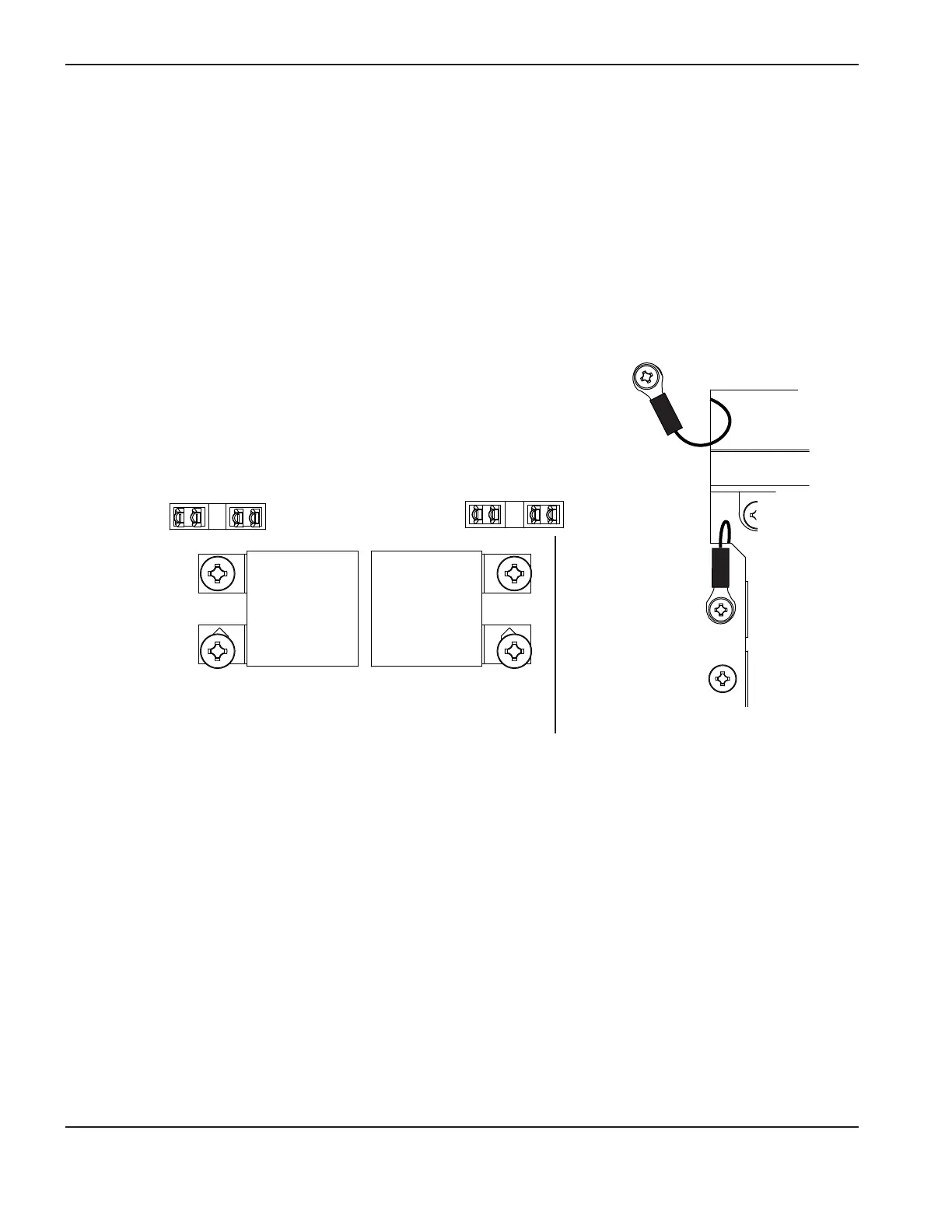
1. Remove PFC temperature sensor connector (J16) from power board.
2. Check the resistance between pins 1 and 2 on the plug. Resistance should be about 5.5kΩ.
3. If the resistance is incorrect, replace the PFC IGBT, gate drive wires, and PFC temperature sensor wire.
4. If the value is correct, measure resistance between pins 1 and 2 on the power board with the temperature sensor
disconnected. The resistance should be about 4.7kΩ.
5. If the value is correct, replace DSP board.
6. If the value is incorrect, replace power board.
BLK
BLK
J13
J16J17J18J19
PFC temperature sensor connection

Table of Contents

Other manuals for Hypertherm Powermax 65

Questions and Answers:

Question and Answer IconNeed help?

Do you have a question about the Hypertherm Powermax 65 and is the answer not in the manual?

Hypertherm Powermax 65 Specifications

General IconGeneral
Open Circuit Voltage (OCV)300 VDC
Gas SupplyClean, dry, oil-free air or nitrogen
Maximum Cut Capacity (Mild Steel)1" (25 mm)
Input Voltage200-600 V, 1/3-PH, 50/60 Hz
Output Current20 – 65 A
Duty Cycle50% @ 65 A
Recommended Gas Inlet Flow Rate/Pressure6.7 scfm @ 85 psi
Torch Lead Length25 ft (7.6 m)
Maximum Cut Capacity (Aluminum)5/8" (16 mm)
Severance Cut Capacity (Mild Steel)1-1/4" (32 mm)
Maximum Severance Thickness1-1/4 in (32 mm)
Gas TypeAir/Nitrogen
Torch OptionsHand Torch, Mechanized Torch

Related product manuals