EasyManuals Logo

Hypertherm Powermax 65 Service Manual

Hypertherm Powermax 65
248 pages
To Next Page IconTo Next Page
To Previous Page IconTo Previous Page
Page #184 background imageLoading...
Page #184 background image
Component ReplaCement
6-2 powermax
65/85
Service Manual
Remove the power supply cover and Mylar barrier
Remove and replace the power supply cover and Mylar
®
barrier
Replacing interior components requires that you remove and replace the power supply cover and Mylar barrier. This
section describes these procedures.
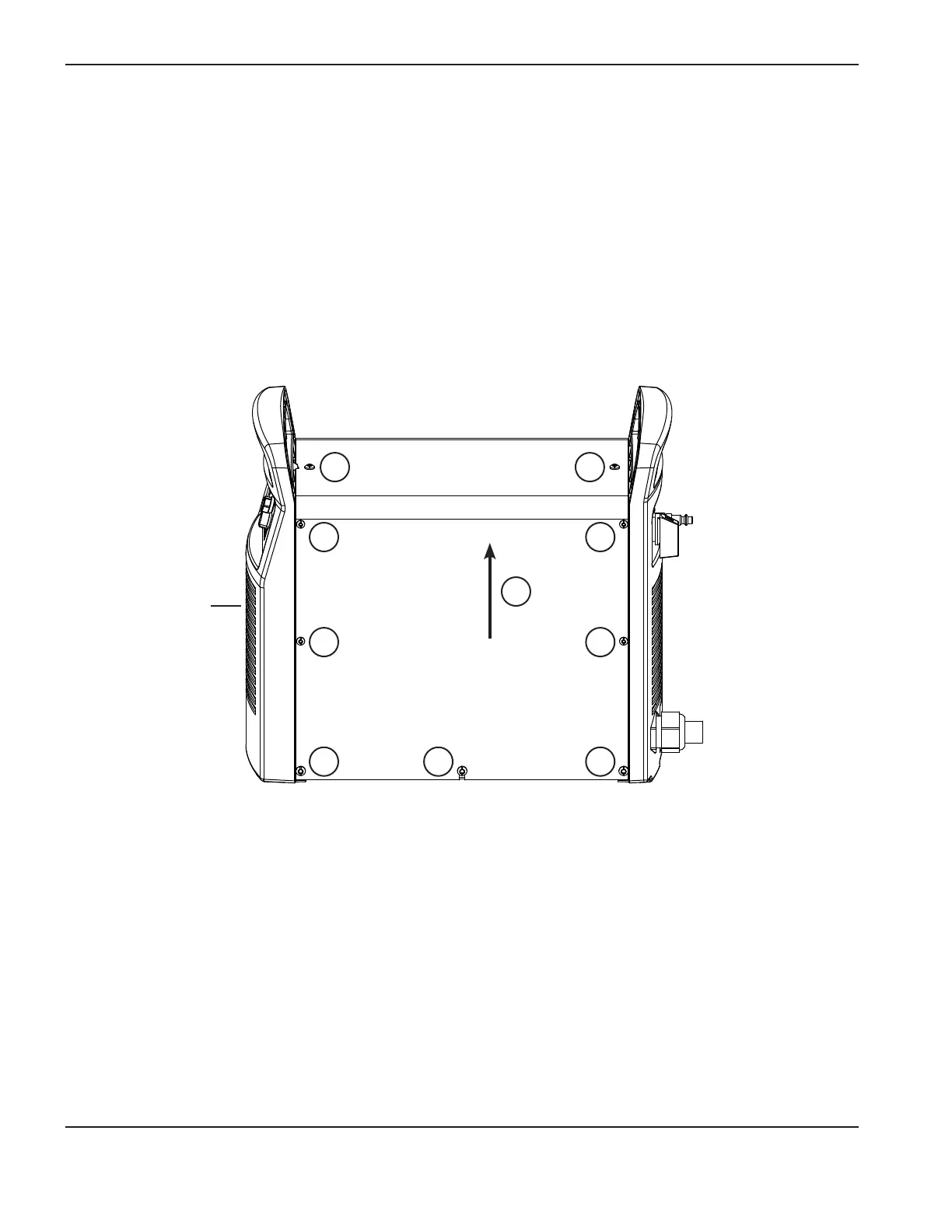
Front of
power supply
1. Turn OFF the power, disconnect the power cord, and disconnect the gas supply.
2. Using a T15 TORX or blade screwdriver, remove the 8 small screws (2) from the power supply cover.
3. Using a T20 TORX or blade screwdriver, remove the 8 large screws (1) from the power supply cover.
4. Lift the cover (3) off the power supply.
1
1 1
2
2
1
2
2
1
3
5. Remove the Mylar barrier from the power-board side of the power supply. The Mylar barrier is flexible and can be
bent slightly for removal.

Table of Contents

Other manuals for Hypertherm Powermax 65

Questions and Answers:

Question and Answer IconNeed help?

Do you have a question about the Hypertherm Powermax 65 and is the answer not in the manual?

Hypertherm Powermax 65 Specifications

General IconGeneral
Open Circuit Voltage (OCV)300 VDC
Gas SupplyClean, dry, oil-free air or nitrogen
Maximum Cut Capacity (Mild Steel)1" (25 mm)
Input Voltage200-600 V, 1/3-PH, 50/60 Hz
Output Current20 – 65 A
Duty Cycle50% @ 65 A
Recommended Gas Inlet Flow Rate/Pressure6.7 scfm @ 85 psi
Torch Lead Length25 ft (7.6 m)
Maximum Cut Capacity (Aluminum)5/8" (16 mm)
Severance Cut Capacity (Mild Steel)1-1/4" (32 mm)
Maximum Severance Thickness1-1/4 in (32 mm)
Gas TypeAir/Nitrogen
Torch OptionsHand Torch, Mechanized Torch

Related product manuals