EasyManuals Logo

Hypertherm Powermax 65 Service Manual

Hypertherm Powermax 65
248 pages
To Next Page IconTo Next Page
To Previous Page IconTo Previous Page
Page #187 background imageLoading...
Page #187 background image
Component ReplaCement
powermax
65/85
Service Manual 6-5
Replace the power cord
For wire sizes, see Extension cord specifications in Section 2, Power Supply Setup.
Replace the power cord (200 – 600 V 3-phase CSA, 400 V 3-phase CE)
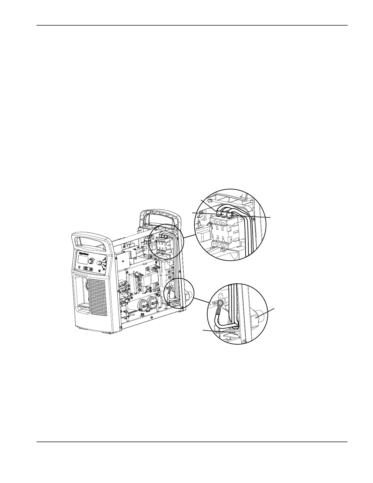
This section describes the procedures for replacing the power cord on 3-phase power supplies.
Remove the existing 3-phase power cord
1. Turn OFF the power, disconnect the power cord, and disconnect the gas supply.
2. Remove the power supply cover and Mylar barrier. Refer to page 6-2 Remove and replace the power supply
cover and Mylar
®
barrier.
3. Loosen the set screws that secure the three power wires to the top of the power switch.
Note: For CSA models, use a #2 Phillips screwdriver. For CE models, use a #1 Phillips screwdriver.
L1
L2
Power switch
Ground screw
Strain relief
retention nut
L3
Strain relief nut
inside power
supply

Table of Contents

Other manuals for Hypertherm Powermax 65

Questions and Answers:

Question and Answer IconNeed help?

Do you have a question about the Hypertherm Powermax 65 and is the answer not in the manual?

Hypertherm Powermax 65 Specifications

General IconGeneral
Open Circuit Voltage (OCV)300 VDC
Gas SupplyClean, dry, oil-free air or nitrogen
Maximum Cut Capacity (Mild Steel)1" (25 mm)
Input Voltage200-600 V, 1/3-PH, 50/60 Hz
Output Current20 – 65 A
Duty Cycle50% @ 65 A
Recommended Gas Inlet Flow Rate/Pressure6.7 scfm @ 85 psi
Torch Lead Length25 ft (7.6 m)
Maximum Cut Capacity (Aluminum)5/8" (16 mm)
Severance Cut Capacity (Mild Steel)1-1/4" (32 mm)
Maximum Severance Thickness1-1/4 in (32 mm)
Gas TypeAir/Nitrogen
Torch OptionsHand Torch, Mechanized Torch

Related product manuals