Component ReplaCement
powermax
65/85
Service Manual 6-7
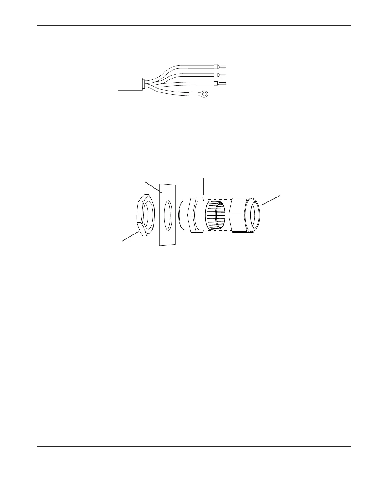
Strain relief
retention nut
Strain relief
Rear panel of
power supply
Strain relief nut
inside power supply
L1 Black
White
Red
Green
L2
L3
#10
1. Slide the strain relief retention nut over the wires of the new power cord and slide it back along the cord.
2. If you are replacing the old strain relief:
a. Slide the new strain relief into the hole in the rear panel of the power supply.
b. Secure the strain relief on the inside of the power supply using the new strain relief nut. Hand tighten the nut
and then over-tighten slightly more.
Install the new 3-phase power cord (CSA model)
3. Route the new power cord wires through the strain relief in the rear panel.
4. Route the black, white, and red wires to the top of the power switch.
5. Insert the wire connectors into the top of the power switch and use a #2 Phillips screwdriver to tighten the set
screws to 10 in-lbs (11.5 kg cm). Refer to the figure above for the correct color assignments. “L1”, “L2”, and “L3”
are marked on the power switch above each set screw.
6. Secure the green ground wire to the heatsink using the Phillips screw and tighten to 20 in-lbs (23.0 kg cm) with the
star washer between the ring terminal and the heat sink.
7. Position the wires in the wire chase up the side of the end panel and out of the way of the power board. Once the
wires are in place, tighten the strain relief retention nut onto the strain relief to secure the new power cord.
Ground (GND)