124 Powermax30 XP Service Manual 808150 Revision 0
6 – Power Supply Component Replacement
Remove and install the pressure switch to J4 wires
1. Complete the following procedures:
a. Set the power switch to OFF (O), disconnect the power cord from the power source, and disconnect the gas
supply.
b. See Remove the power supply cover on page 88.
2. Remove the red-and-black wires from the pressure switch.
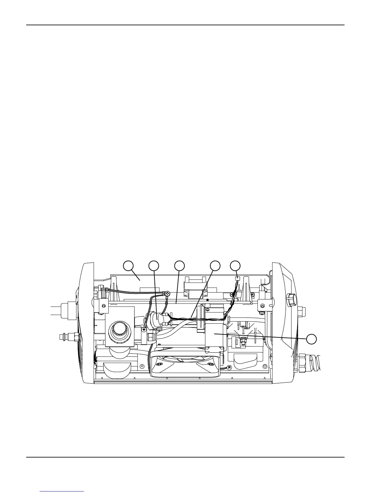
3. The other end of the red-and-black wire pair is connected to the power board at J4. (See Figure 59.) Lift the top
edge of the component barrier and disconnect the wire pair by pulling the connector straight back away from the
board.
4. Connect the new wire to the power board at J4, and route the wires through the notch in the center panel that is
nearest the solenoid valve. (See Figure 59.)
5. Press the black wire’s connector onto the pressure switch pin that is nearest the center panel.
6. Press the red wire’s connector onto the pressure switch pin that is farthest from the center panel.
7. Complete the following procedures:
a. See Install the power supply cover on page 89.
b. Reconnect the gas supply and power cord, and set the power switch to ON (I).
Figure 59
1
Solenoid valve
2
J4 connector on the power board
3
Pressure switch to J4 wire pair
4
Center panel
5
Pressure switch
6
Power board