Powermax30 XP Service Manual 808150 Revision 0 69
5 – Troubleshooting and System Tests
Control board LEDs
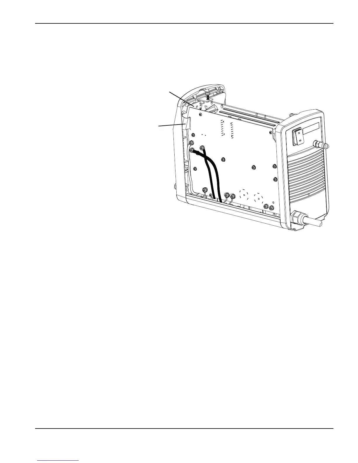
The Powermax30 XP control board (PCB1) is located inside of the front panel.
Figure 9
The control board has four diagnostic LEDs:
Reset – This LED illuminates when a voltage reading is out of range or the Reset LED blinks.
Error – This LED illuminates when the gas pressure, torch cap, or temperature LEDs on the front of the power
supply illuminate. If all four LEDs on the front of the power supply are blinking, the Error LED also blinks. The number
of blinks between pauses indicates which component may have failed.
Transfer – This LED illuminates when there is proper arc transfer between the torch and the workpiece, and blinks
during continuous pilot arc operation (such as when cutting expanded metal or moving the arc off the plate and then
back on).
Start – This LED illuminates when the power supply receives a start signal and remains illuminated during normal
operation.
Control board
Ribbon cable