Powermax30 XP Service Manual 808150 Revision 0 61
5 – Troubleshooting and System Tests
5. Check the output resistance for the values shown in the following table.
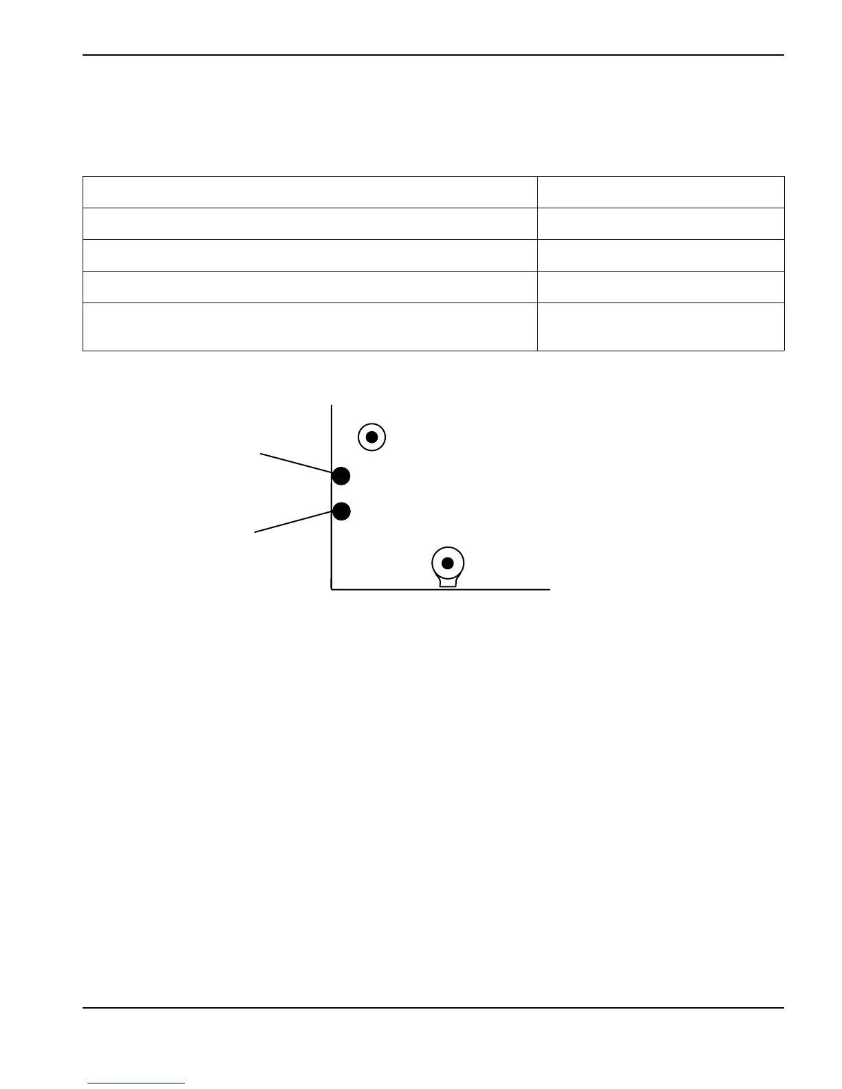
J16 and J17 are labeled on the component side of the power board. See Figure 7 for
locations on the back side of the power board.
Figure 7
6. If you do not find any problems during the visual inspection or the initial resistance check, and the power supply is still
not operating correctly, see Troubleshooting guide on page 63.
Measure resistance from Approximate values
Work lead (J22) to nozzle (J16, red wire) 100 kΩ
Work lead (J22) to electrode (J17, white wire) 20 kΩ
Electrode (J17, white wire) to nozzle (J16, red wire) 120 kΩ
Work lead (J22), nozzle (J16, red wire), and electrode (J17, white wire) to
ground
>20MΩ