Powermax30 XP Service Manual 808150 Revision 0 73
5 – Troubleshooting and System Tests
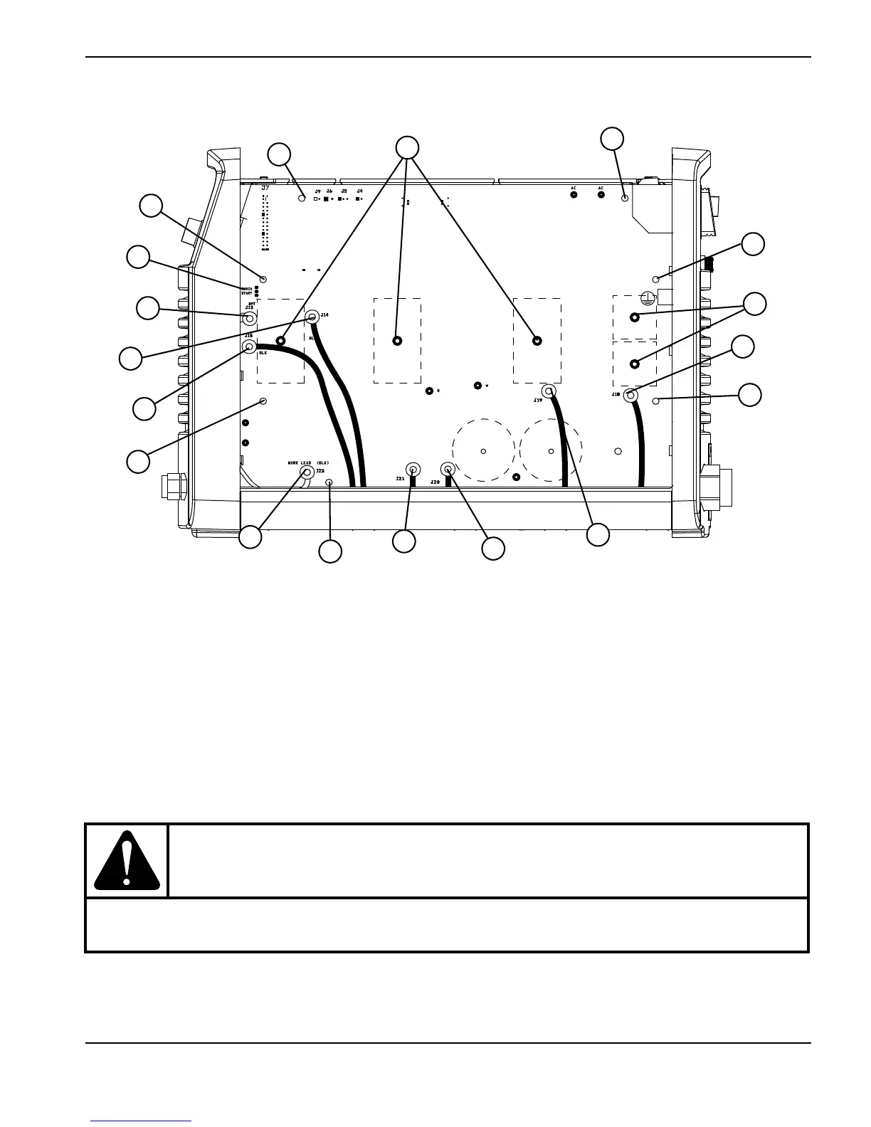
Figure 13
WARNING!
Voltages of up to 50 VDC continue to be present on the DC bus for at least 30 seconds after
disconnecting the input power. Allow bus voltages to dissipate before performing any tests.
WORK LEAD (BLK)
BLK
BLK
TORCH
START
AC AC
R
w
1
Retaining screw (3)
2
Heatsink assembly screw (4)
3
Torch start and cap-sensor (J12)
4
J13
5
J14
6
J15
7
Work lead connector (J22)
8
J21
9
J20
10
J19
11
J18
12
Input diode bridge screws (2)
13
IGBT screws (3)